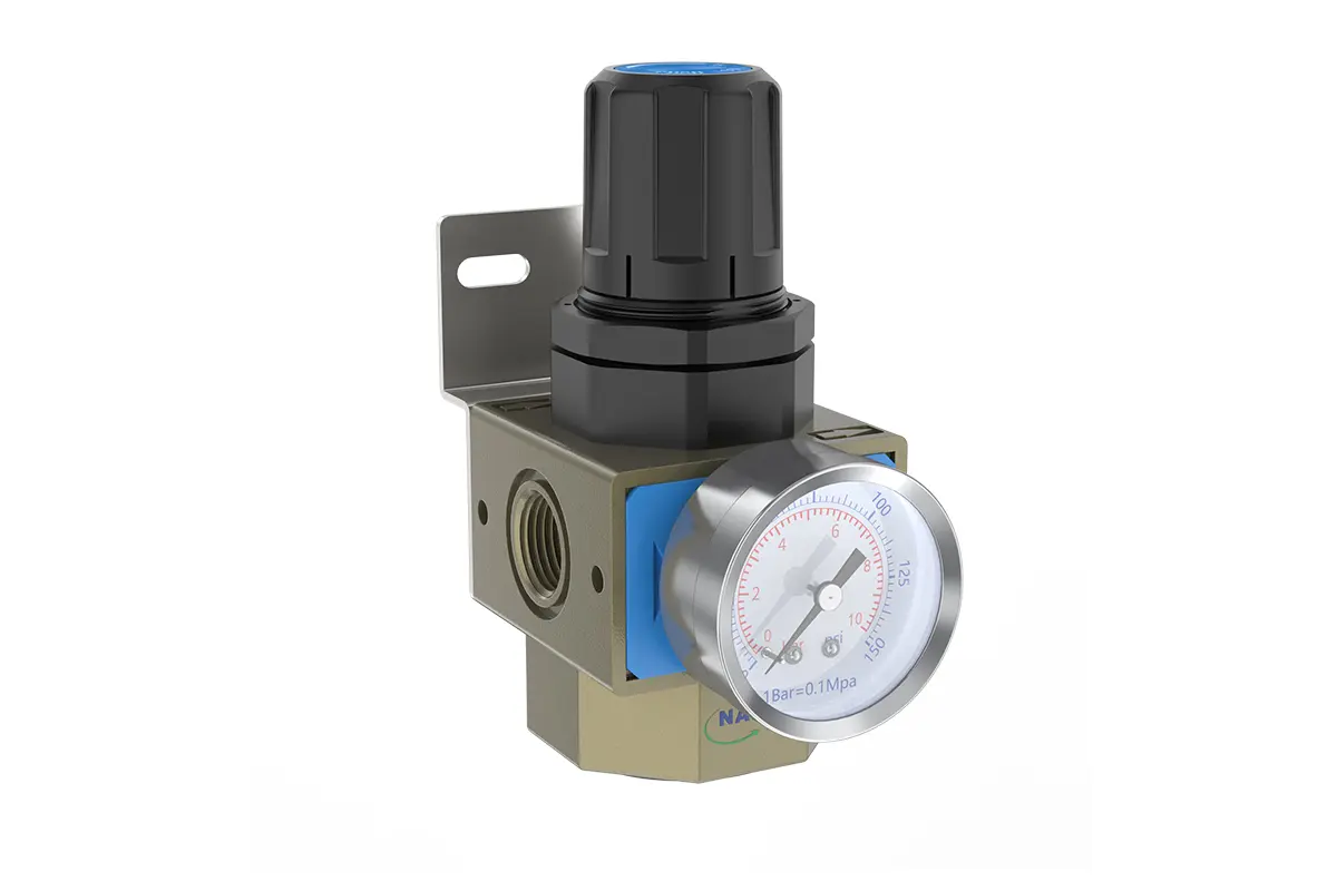
UR-02/03/04 1/4" 3/8" 1/2" AR Air Regulator
description1
UR-02/03/04 1/4" 3/8" 1/2" AR Air Regulator
UR-02/03/04 1/4" 3/8" 1/2" AR Air Regulator
NANPUUR-02/03/04 1/4" 3/8" 1/2" AR Air Regulator
| UR | 02 | BSP | |
| Series Number | Body Size | Port Size | Thread Type |
| 02 | 1/4" | BSP | |
| 03 | 3/8" | NPT | |
| 04 | 1/2" | PT |
NANPUTechnical Specifications
| Technical Specifications | |
| Max Input Pressure | 1.2Mpa{12.24kgf/cm²} /174.04Psi |
| Max Operating Pressure | 1.0Mpa{10.2kgf/cm²} /145Psi |
| Temperature Range | -5~60℃ |
| Pressure Range | UR-02~04:0.05~0.85Mpa(0.51~8.7kgf/cm² ) |
| Model | Specification |
| UR-02 | 2080 |
| UR-03 | 2100 |
| UR-04 | 2600 |
| Product Benefits |
| The assembly of all calibration shall meet the maximum flow requirement. Please clean the port and fitting before installation, it will effectively avoid bring dust to the air path. Pay attention to direction of air flow and arrow pointing on product body if correct, minding port and thread size if match. |
NANPUPreparation

All calibration assemblies shall strictly comply with the maximum flow rate parameters specified in the technical specifications. Such compliance is vital for ensuring optimal system performance and operational reliability.
Prior to installation, all ports and fittings must undergo thorough cleaning using approved cleaning agents and standardized procedures. This rigorous cleaning protocol effectively eliminates dust, debris, and contaminants from the air passages, preserving the integrity and operational efficiency of the compressed air system.
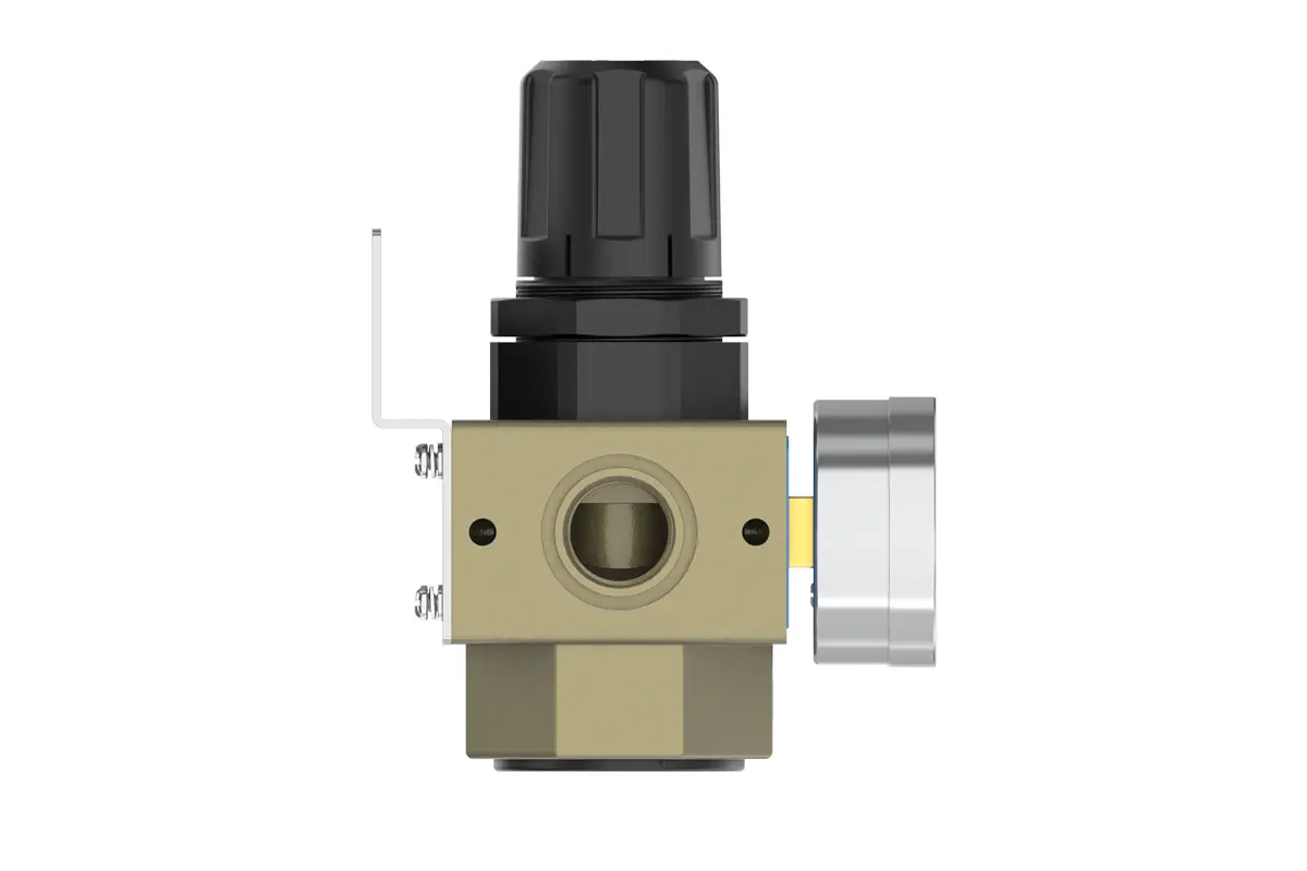
During installation, comprehensive verification shall be performed to ensure the airflow direction precisely matches the arrow indicators on the product housing. Additionally, port and thread dimensions must be accurately validated against mating components. This meticulous confirmation of flow orientation and dimensional compatibility is essential to prevent installation-induced errors that may cause system malfunctions or inefficiencies.
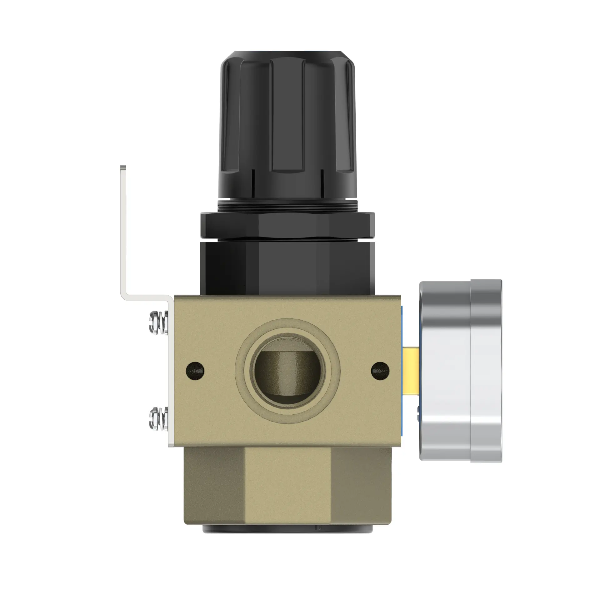
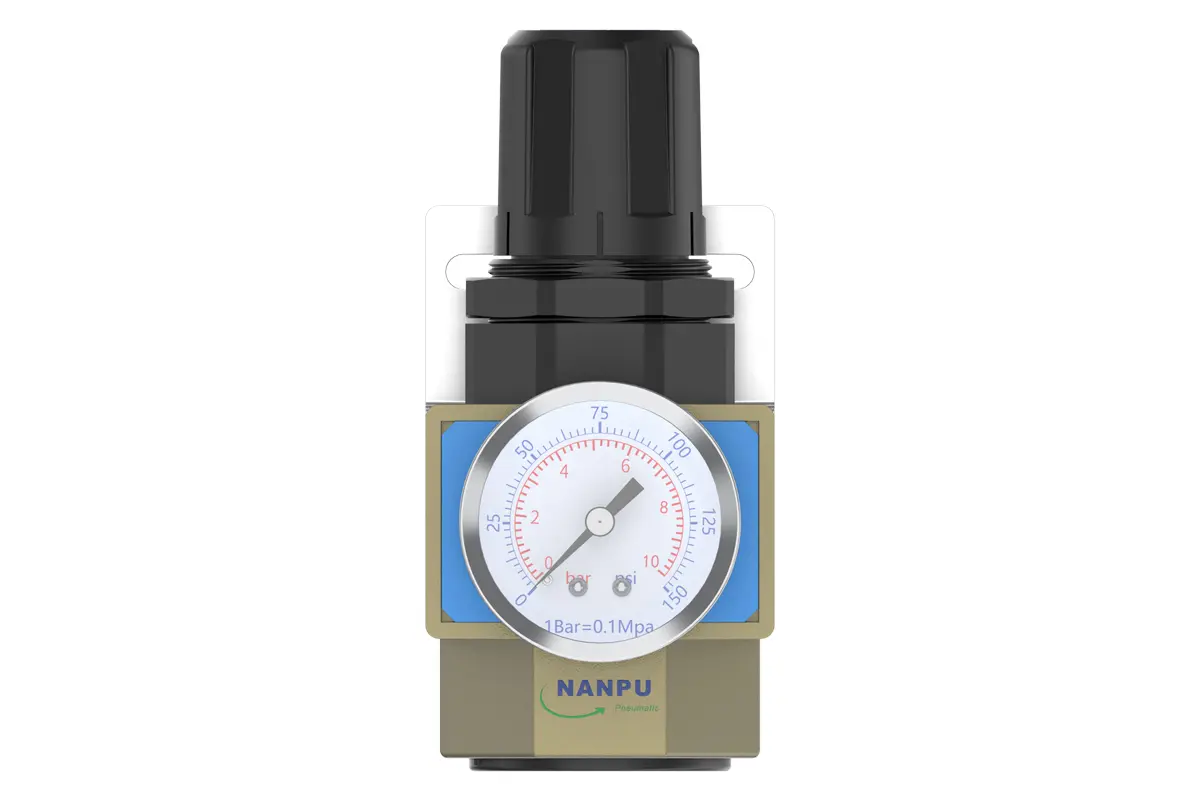
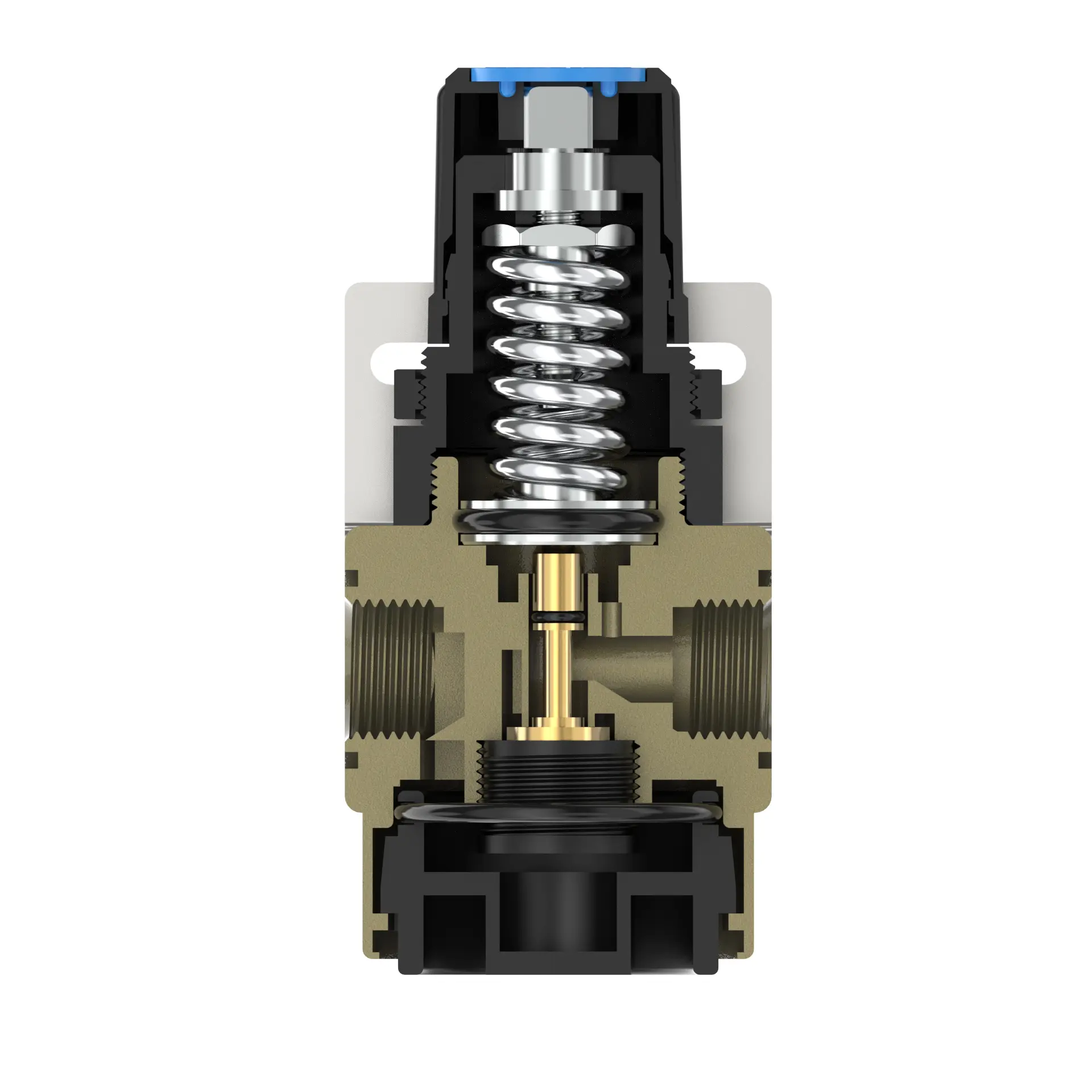
To adjust pressure, first elevate the gauge knob to its unlocked position. Proceed to rotate the knob for pressure calibration: clockwise rotation induces gradual, steady pressure elevation, while counterclockwise rotation effects steady pressure reduction.
Monitor the pressure gauge closely and cease rotation immediately upon reaching the target pressure. Post-calibration, firmly engage the knob to lock the setting. Improperly secured knobs may compromise sealing integrity, risking leakage that could impair system performance and safety. Conduct regular operational inspections of the locked knob to ensure pressure stability within specified thresholds.