


UFRL-02;03;04 1/4" 3/8" 1/2" F.R.L.Combination Air Filter, Regulator & Lubricator
description1
UFRL-02;03;04 1/4" 3/8" 1/2" F.R.L.Combination Air Filter, Regulator & Lubricator
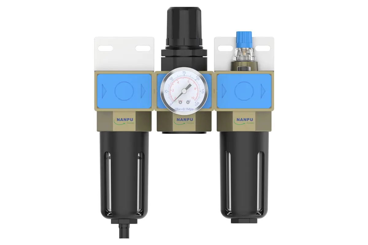
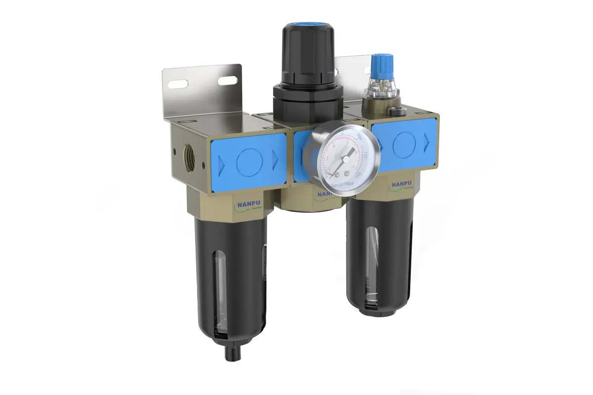
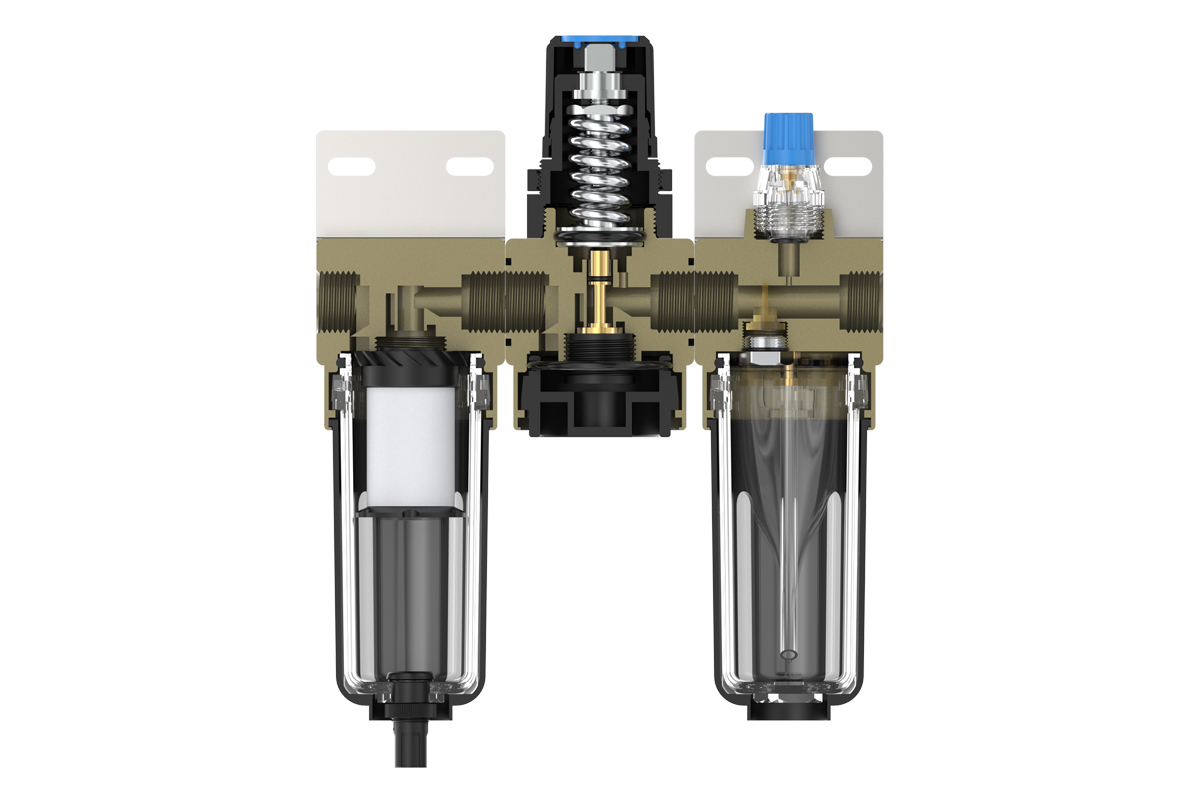
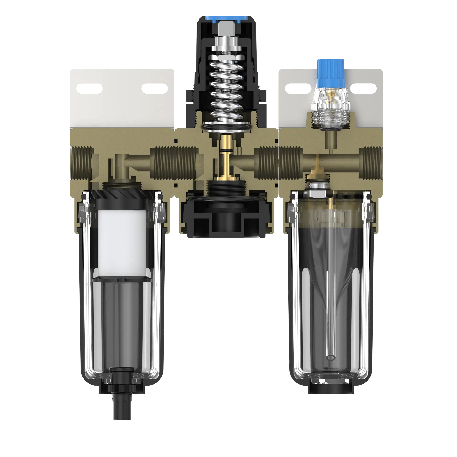
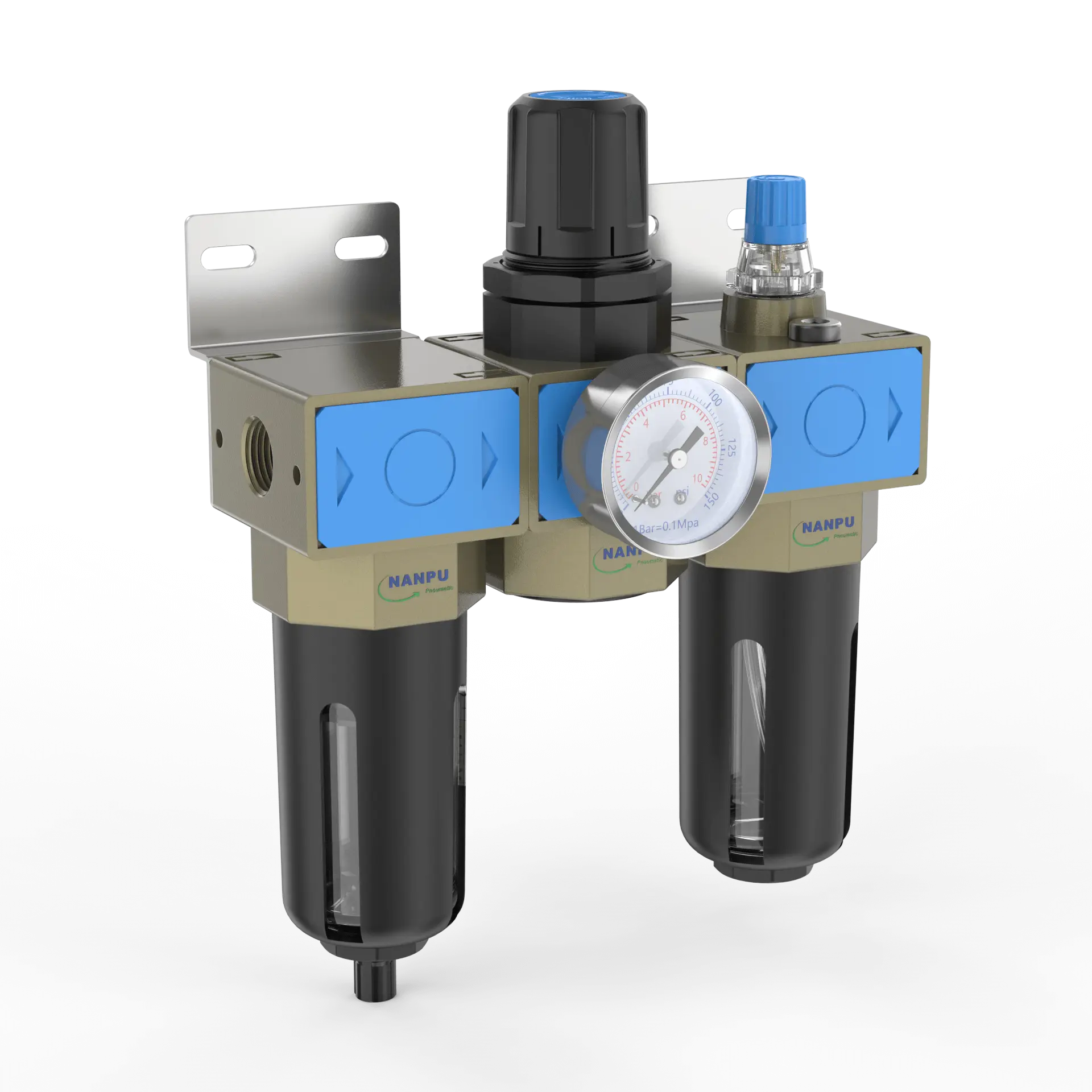
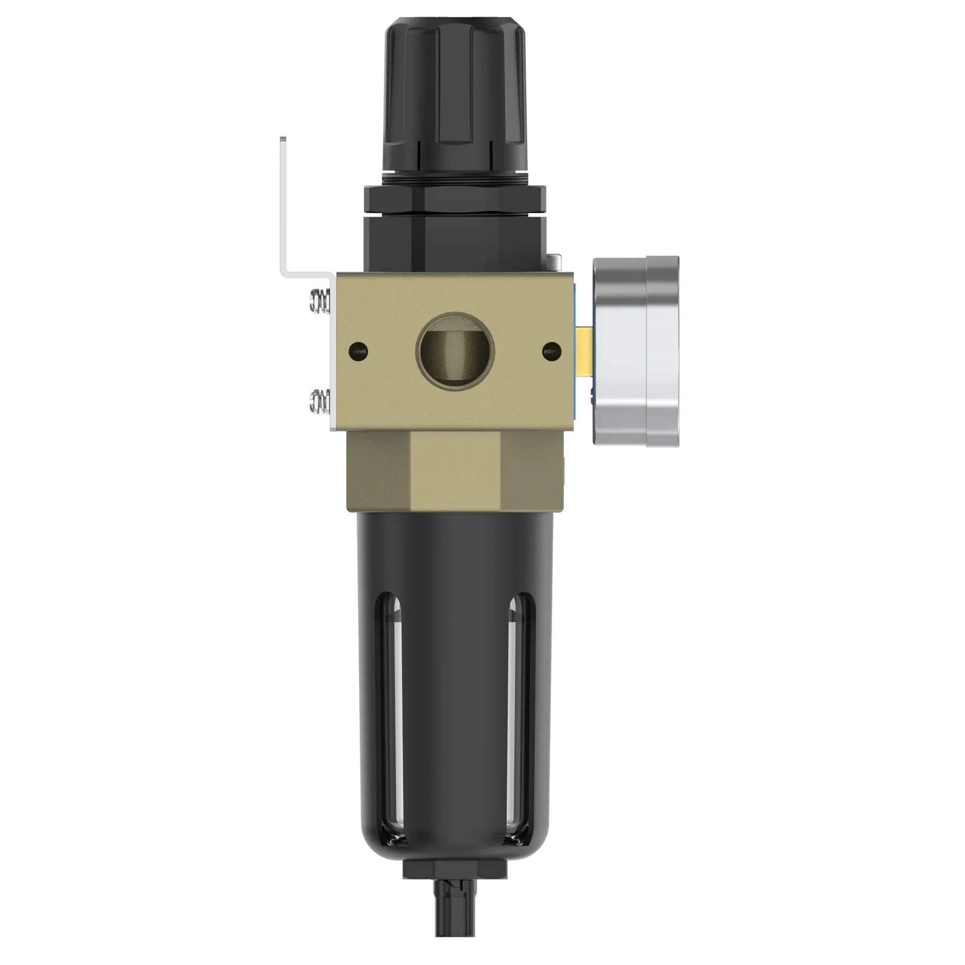
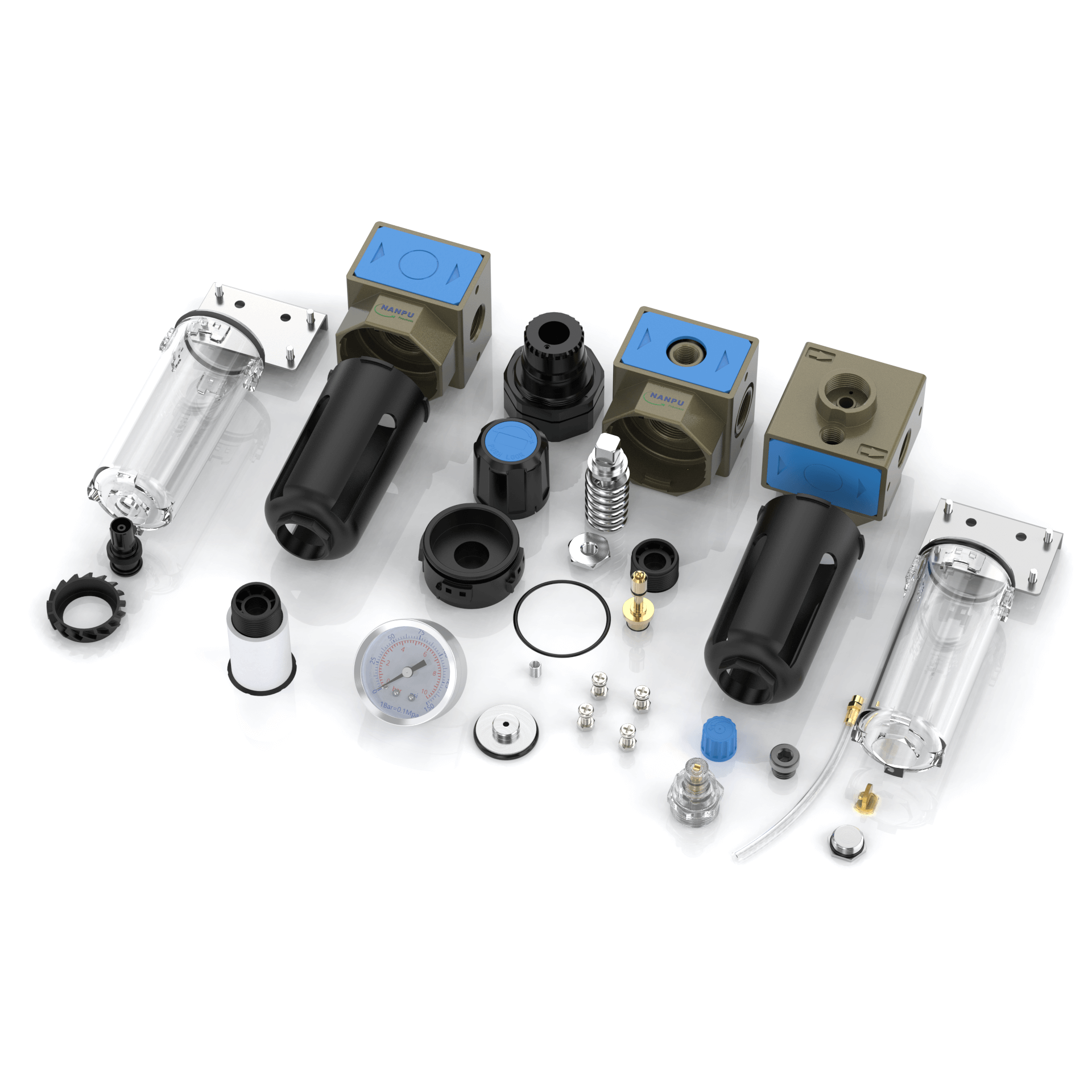
The Filter-Regulator-Lubricator (FRL) assembly constitutes a three-component integrated system. The filter is meticulously engineered to eliminate the majority of liquid and solid particulates from compressed air streams. The pressure-reducing regulator operates to precisely control outlet pressure. The lubricator, in turn, dispenses lubricant to pneumatic equipment, thereby significantly prolonging their operational lifespan.
NANPUUFRL-02;03;04 1/4" 3/8" 1/2" F.R.L.Combination Air Filter, Regulator & Lubricator
| UFR/L- | 03 | BSP | D |
| Series Number | Port Size | Thread Type | Drainage Method |
| 02:1/4" | BSP | Blank: Differential Pressure Drain | |
| 03:3/8" | NPT | A: Manual Drain | |
| 04:1/2" | PT | D: Auto Drain | |
| 06: 3/4" | |||
| 10: 1" |
NANPUTechnical Specifications
| Technical Specifications | |
| Max Input Pressure | 1.2Mpa{12.24kgf/cm²} /174.04Psi |
| Max Operating Pressure | 1.0Mpa{10.2kgf/cm²} /145Psi |
| Temperature Range | 5~60℃ |
| Filtration Accuracy | 0.01μm、 5μm、40μm |
| Bowl Material | Polycarbonate |
| Suggested Oil | Turbine Oil No. 1 ISO-VG32 |
| Pressure Range | 0.05~0.85Mpa(0.51~8.7kgf/cm² )/0~125Psi |
| Model | Model | |
| Manual Drain | Auto Drain | (L/min)Rated Flow Rate |
| UFRL-02 | UFRL-02D | 2080 |
| UFRL-03 | UFRL-03D | 2100 |
| UFRL-04 | UFRL-04D | 2600 |
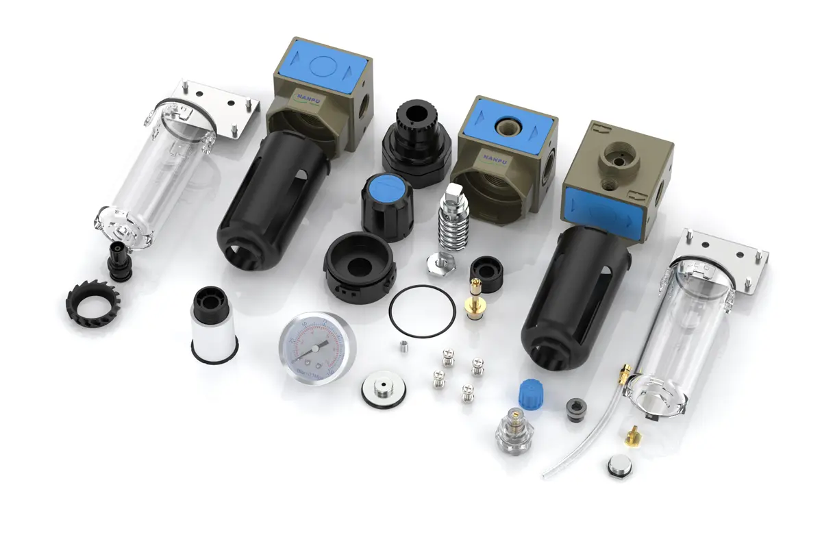
| Product Benefits |
| All Portsize Piggyback Air Filter (5 Micron Element Standard), Regulator & Lubricator (FRL) |
| Dry Air, Pressure Regulating & Lubricate Air |
| Temperature Range: 41-140℉ (5-60℃) |
NANPUUFRL-02;03;04 1/4" 3/8" 1/2" F.R.L.Combination Air Filter, Regulator & Lubricator
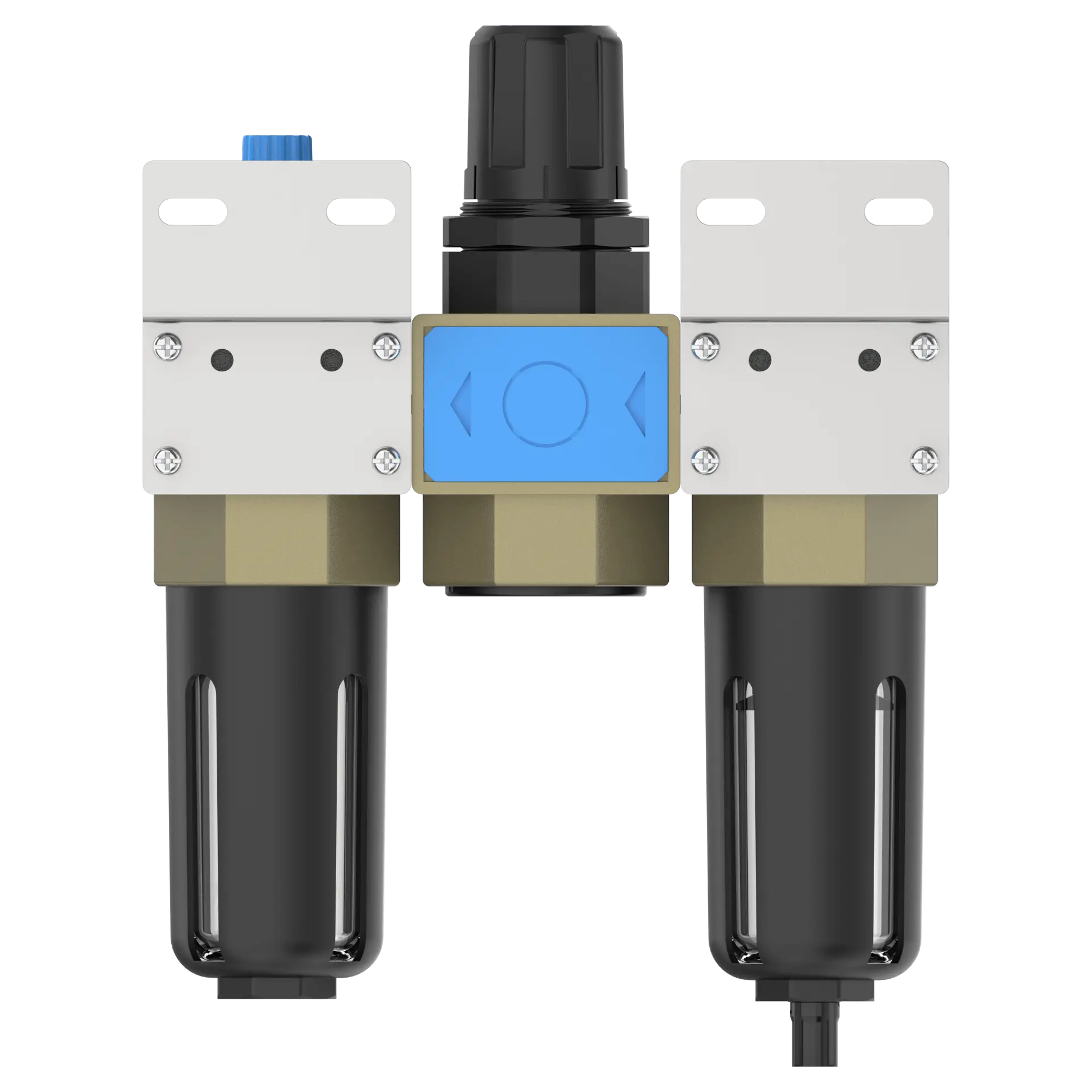
Manual Drain UFRL-02;03;04 1/4" 3/8" 1/2" F.R.L.Combination Air Filter, Regulator & Lubricator
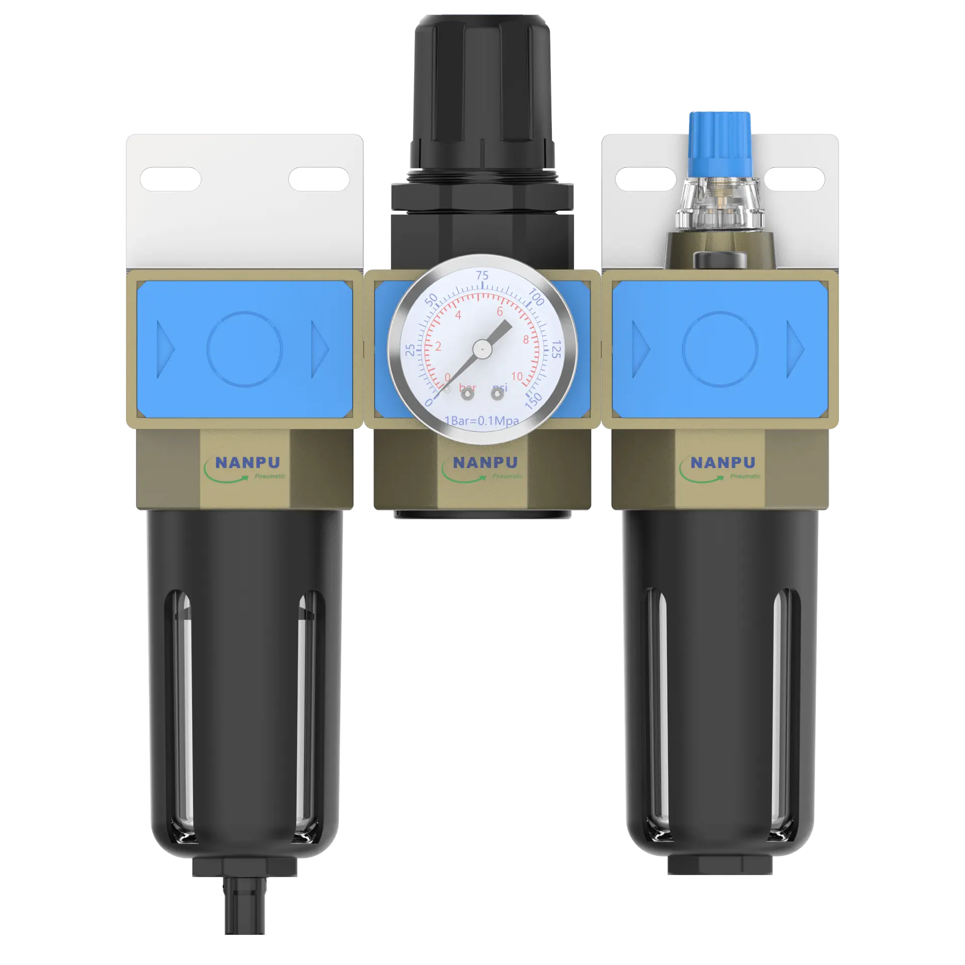
Auto Drain UFRL-02D;03D;04D 1/4" 3/8" 1/2" F.R.L.Combination Air Filter, Regulator & Lubricator
1.Preparation
All calibration assemblies must conform to maximum flow rate specifications.
Prior to installation, all ports and fittings require meticulous cleaning to prevent dust ingress into air passages.
Verify that airflow direction aligns with arrow indicators on the product body, and ensure proper matching of port and thread dimensions.
2. Pressure Adjustment
Lift the pressure gauge knob and initiate rotation. A clockwise turn effects a gradual, stepwise pressure increase, whereas a counterclockwise rotation effects pressure decrement.
Once the target pressure value is reached, cease rotation and firmly depress the knob to lock it in place. Failure to perform this securing procedure may give rise to pressure leakage issues.
3. Dial Reading
The pressure gauge must be securely mounted to the main assembly. During pressure adjustment, the gauge should be closely monitored to ensure that the readings exhibit smooth and unobstructed fluctuations."
4.Drainage
The drainage column operates in a self-actuating mode, automatically opening to expel contents under pressure absence and closing during airflow. When the water level exceeds the upper limit, immediate drainage is imperative; non-adherence will compromise dehumidification efficiency. The fitting on the drain head is configured for air hose attachment and may be removed per operational specifications."
5.Oil Adjustment
Rotation of the needle valve in the clockwise (""+"") direction increases the oil suction rate. Conversely, counterclockwise (""-"") rotation of the needle valve reduces or terminates the oil suction process."
6.Refueling
Rotate the filling screw clockwise, ensuring the oil volume added does not exceed 80% of the bowl capacity. Upon completion of refueling, securely fasten the filling screw.