


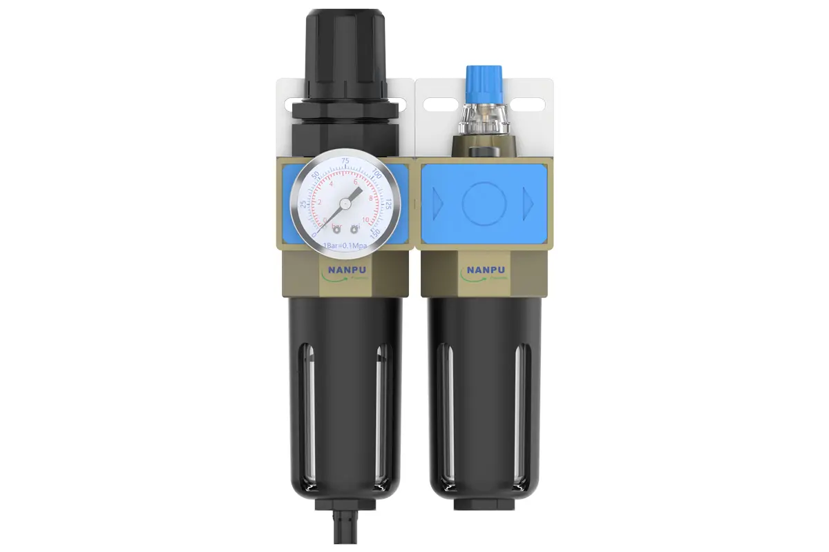
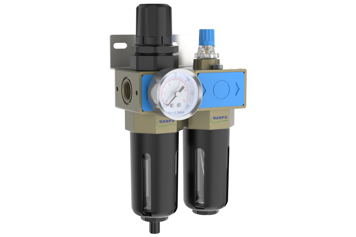
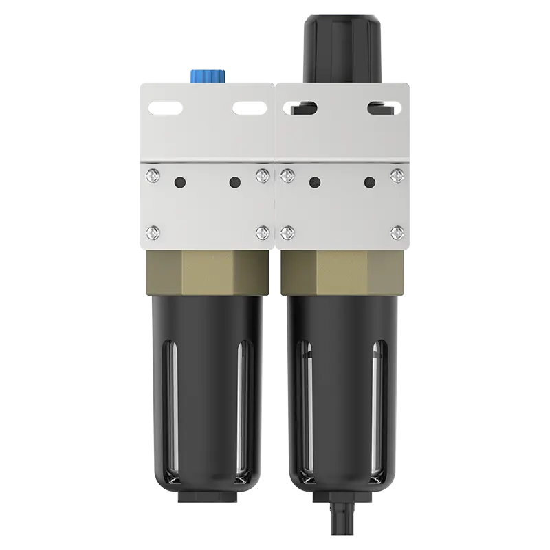
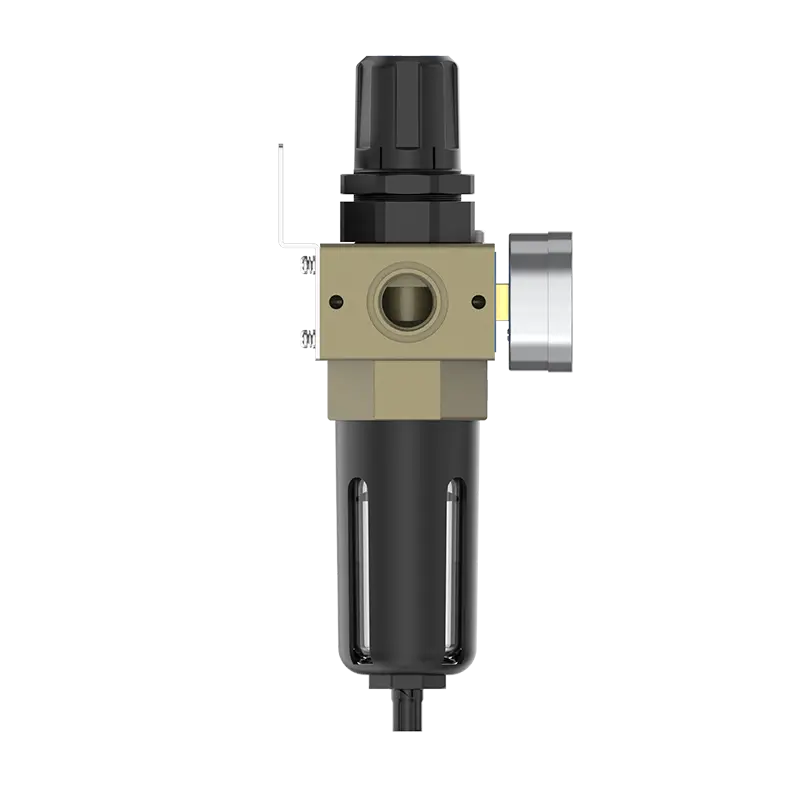
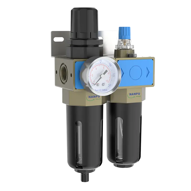
UFR/L-02;03;04 1/4" 3/8" 1/2" F.R.L.Combination Air Filter, Regulator & Lubricator
description1
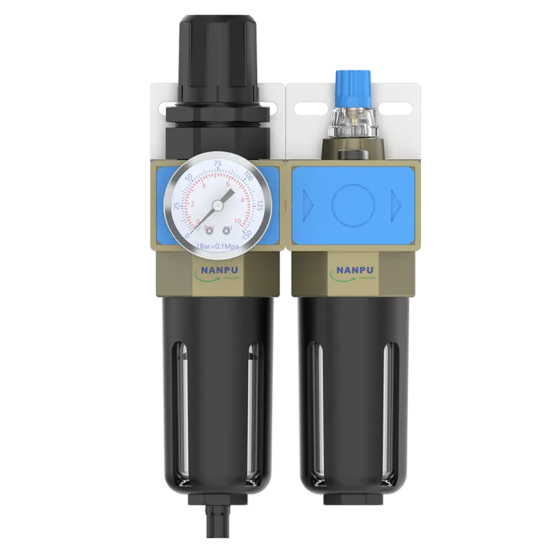
UFR/L-02;03;04 1/4" 3/8" 1/2" F.R.L.Combination Air Filter, Regulator & Lubricator
Auto Drain UFR/L-02D;03D;04D 1/4" 3/8" 1/2" F.R.L.Combination Air Filter, Regulator & Lubricator
NANPUUFR/L-02;03;04 1/4" 3/8" 1/2" F.R.L.Combination Air Filter, Regulator & Lubricator
| UFR/L- | 03 | BSP | D |
| Series Number | Port Size | Thread Type | Drainage Method |
| 02:1/4" | BSP | Blank: Differential Pressure Drain | |
| 03:3/8" | NPT | A: Manual Drain | |
| 04:1/2" | PT | D: Auto Drain | |
| 06: 3/4" | |||
| 10: 1" |
NANPUTechnical Specifications
| Technical Specifications | ||
| Max Input Pressure | 1.2Mpa{12.24kgf/cm²} /174.04Psi | |
| Max Operating Pressure | 1.0Mpa{10.2kgf/cm²} /145Psi | |
| Temperature Range | 5~60℃ | |
| Filtration Accuracy | 0.01μm、 5μm、40μm | |
| Bowl Material | Polycarbonate | |
| Suggested Oil | Turbine Oil No. 1 ISO-VG32 | |
| Pressure Range | 0.05~0.85Mpa(0.51~8.7kgf/cm² )/0~125Psi |
| Model | Model | |
| Manual Drain | Auto Drain | (L/min)Rated Flow Rate |
| UFR/-02 | UFR/-02D | 2080 |
| UFR/-03 | UFR/-03D | 2100 |
| UFR/-04 | UFR/-04D | 2600 |
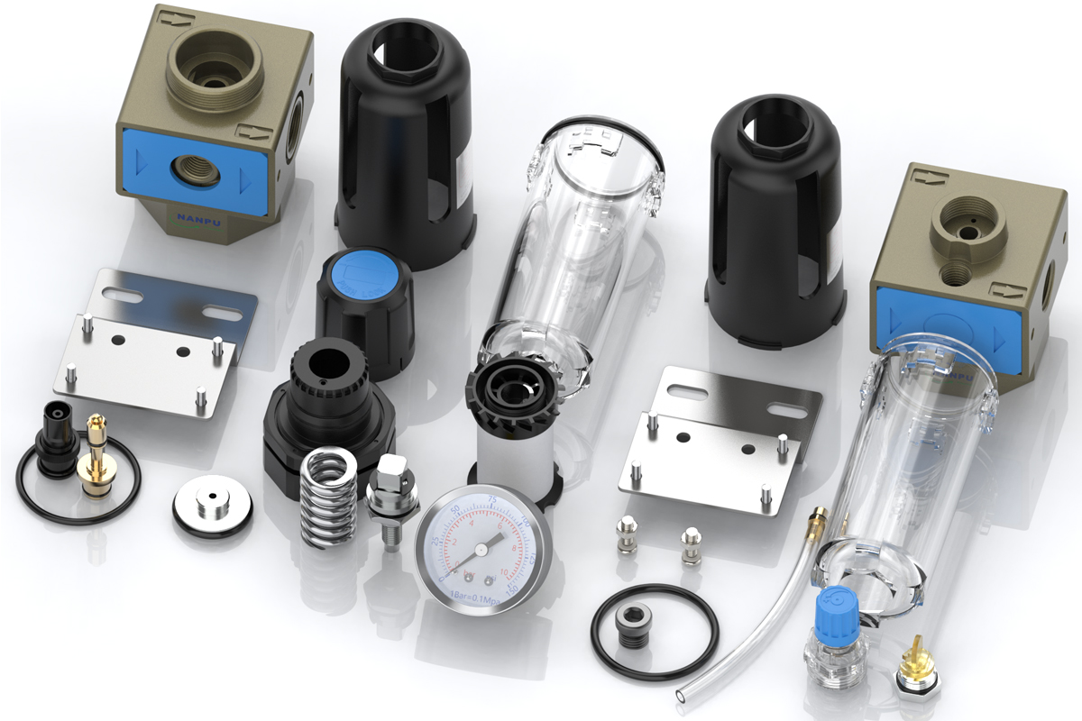
| Product Benefits |
| All Portsize Piggyback Air Filter (5 Micron Element Standard), Regulator & Lubricator (FRL) |
| Dry Air, Pressure Regulating & Lubricate Air |
| Temperature Range: 41-140℉ (5-60℃) |
"1.Preparation
All calibration assemblies shall adhere to the maximum flow rate specification.
Prior to installation, all ports and fittings shall be meticulously cleaned to effectively prevent dust ingress into the air passage.
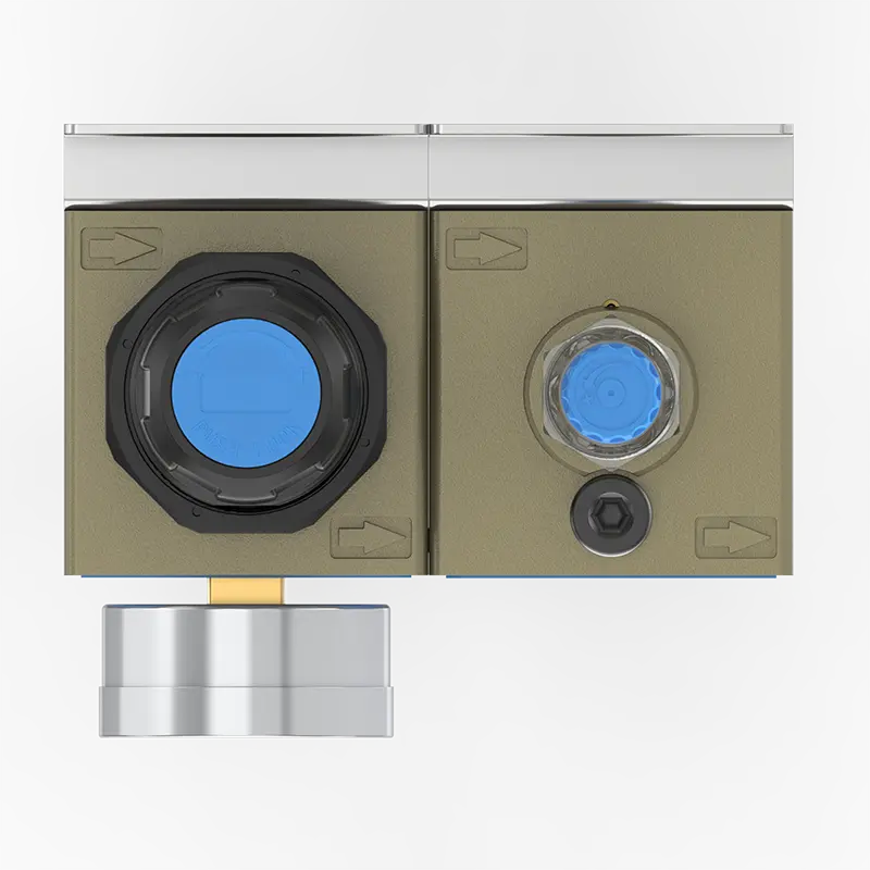
Confirm that the air flow direction corresponds with the arrow indications on the product body, and ensure proper matching of port and thread dimensions."
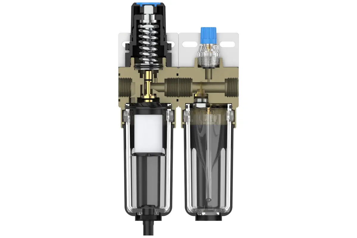
"2. Pressure Adjustment
Raise the pressure gauge knob and commence rotation. A clockwise turn effects a steady, incremental pressure increase, while a counterclockwise rotation induces pressure reduction.
Upon attaining the target pressure value, halt rotation and firmly depress the knob to lock it in position. Neglecting this securing procedure may precipitate pressure leakage complications."
"3. Dial Reading
The pressure gauge shall be rigidly mounted to the main assembly. During pressure adjustment, the gauge shall be carefully observed to confirm that the readings demonstrate smooth and unimpeded variations."
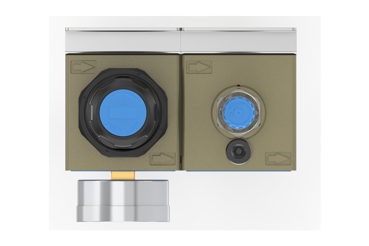
"4.Drainage
The drainage column functions in a self-actuating mode, automatically opening to expel contents when pressure is absent and closing during airflow. Should the water level surpass the upper limit, immediate drainage is mandatory; non-compliance will impair dehumidification efficacy. The fitting on the drain head is configured for air hose attachment and may be removed according to operational specifications."
"5.Oil Adjustment
Rotate the needle valve clockwise (in the ""+"" direction) to enhance the oil suction rate. Conversely, rotating the needle valve counterclockwise (in the ""-"" direction) will diminish or terminate the oil suction process."
"6.Refueling
Turn the fueling screw clockwise, ensuring the oil volume added does not exceed 80% of the bowl's capacity. Upon completion of the refueling, tightly secure the fueling screw."