


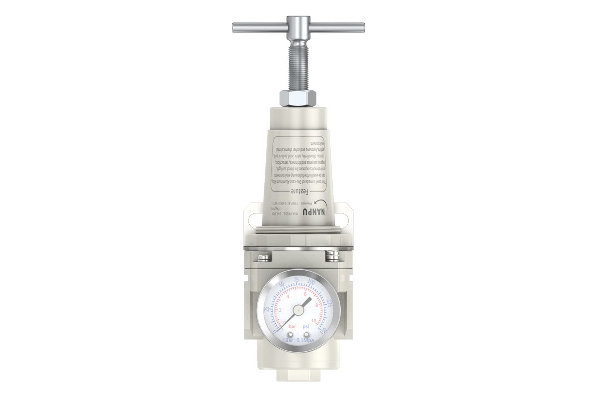
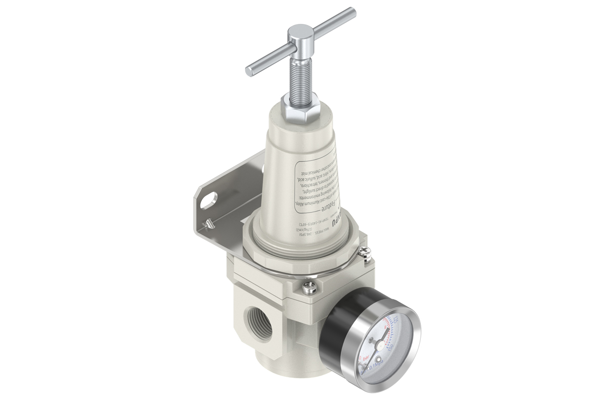
TR3000-02/03 TR4000-04/06 3/8" 1/2" 3/4" Air Regulator
description1
TR3000-02/03 TR4000-04/06 3/8" 1/2" 3/4" Air Regulator
NANPUTR3000-02/03 TR4000-04/06 3/8" 1/2" 3/4" Air Regulator
| TW | 3000 | MINI | BSP |
| Series Number | Port Size | Thread Type | |
| 3000 | 02:1/4" 03:3/8" | BSP | |
| 4000 | 04:1/2" 06:3/4" | NPT | |
| PT |
NANPUTechnical Specifications
| Technical Specifications | ||
| Max Input Pressure | 2.0Mpa{20.39kgf/cm²} 290Psi | |
| Max Operating Pressure | 1.8Mpa{18.35kgf/cm²} 261Psi | |
| Temperature Range | 5~60℃ | |
| Pressure Range | TC3000~4000:0.05~1.8Mpa(0.51~18.35kgf) |
| Model | Specification |
| TR3000-02 | 500 |
| TR3000-03 | 2000 |
| TR4000-04 | 2000 |
| TR4000-06 | 4000 |
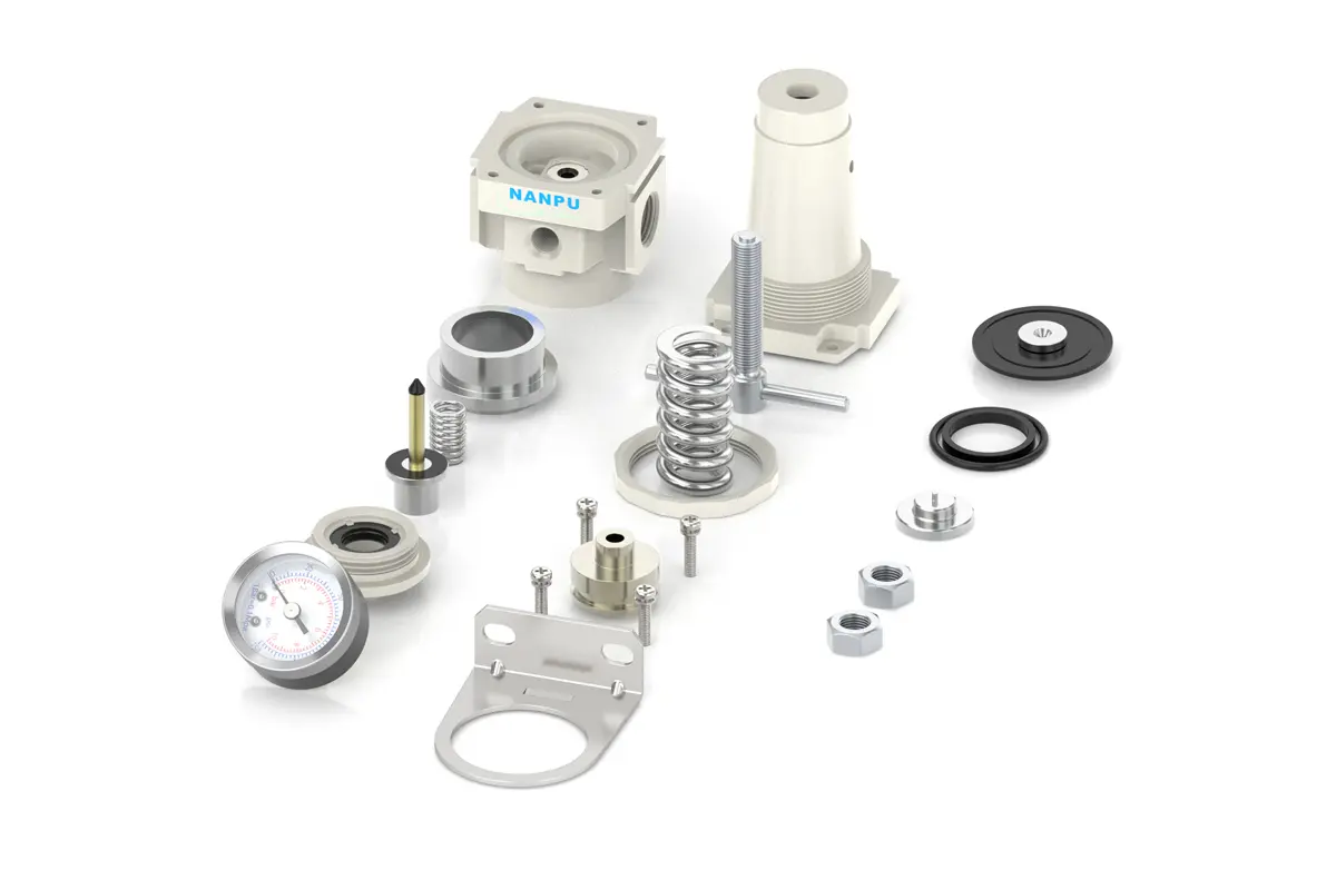
| Product Benefits |
| NANPU Air Regulator is a ideal product provide best using experience ever.Use with any compressor, air tank or air system to precisely regulate and maintain constant air pressure to your tools and equipment. |
All calibration assemblies must be precisely configured to fully meet the maximum flow rate specifications outlined in the technical documentation. Such compliance is critical for preserving the operational efficiency and performance integrity of the entire system.
Prior to installation, thorough cleaning of all ports and fittings is imperative. Utilize suitable cleaning agents and protocols to eliminate debris, contaminants, or residues. This comprehensive cleaning procedure acts as a key preventive measure, effectively mitigating the risk of dust or particulates entering the air pathway—potential causes of system inefficiencies, blockages, or premature degradation.
During installation, strict attention must be paid to airflow direction alignment. Carefully confirm that airflow direction exactly matches the arrow indicators on the product housing. Additionally, a detailed inspection of port and thread dimensions is required to ensure a proper, secure fit. Any dimensional mismatches or misalignments may lead to leakage, diminished performance, or potential system failures. Adherence to these installation protocols enables confident system assembly, ensuring optimal functionality and reliability.
To begin the pressure adjustment process, first lift the pressure gauge knob to its unlocked position. Next, execute rotational adjustments with precision: clockwise rotation effects a steady, incremental pressure increase, while counterclockwise rotation produces a corresponding decrease. Close monitoring of pressure gauge readings throughout this procedure is mandatory.
Upon reaching the target pressure specified in the operational protocols, immediately halt all rotational adjustments. To secure the set pressure and prevent inadvertent deviations, firmly engage the knob in its fully locked position. Improper locking of the knob may compromise the seal, elevating leakage risks. Such leakage not only impairs pressure setting accuracy but also introduces potential safety hazards and could damage interconnected equipment or system components. Regularly inspect the locked knob during operation to maintain the pressure regulation system’s stability and integrity.
Proper installation of the pressure gauge onto the main body requires precise torque application in accordance with specified parameters, using appropriate tools and methodologies. This rigorous installation protocol ensures a secure, leak-tight connection, mitigating risks of displacement or loosening during operational use.
Throughout the pressure adjustment phase, continuous, attentive monitoring of the pressure gauge is imperative. Closely observe to confirm that readings fluctuate smoothly and consistently—without abrupt spikes, hesitations, or irregular variations. Any deviation from such smooth behavior may signal underlying issues, including internal blockages within the gauge, damage to its internal mechanisms, or calibration inaccuracies. Prompt investigation and remediation of these anomalies are critical to preserving the pressure measurement system’s precision and dependability, thereby safeguarding the optimal performance and safety of the entire equipment or process.