


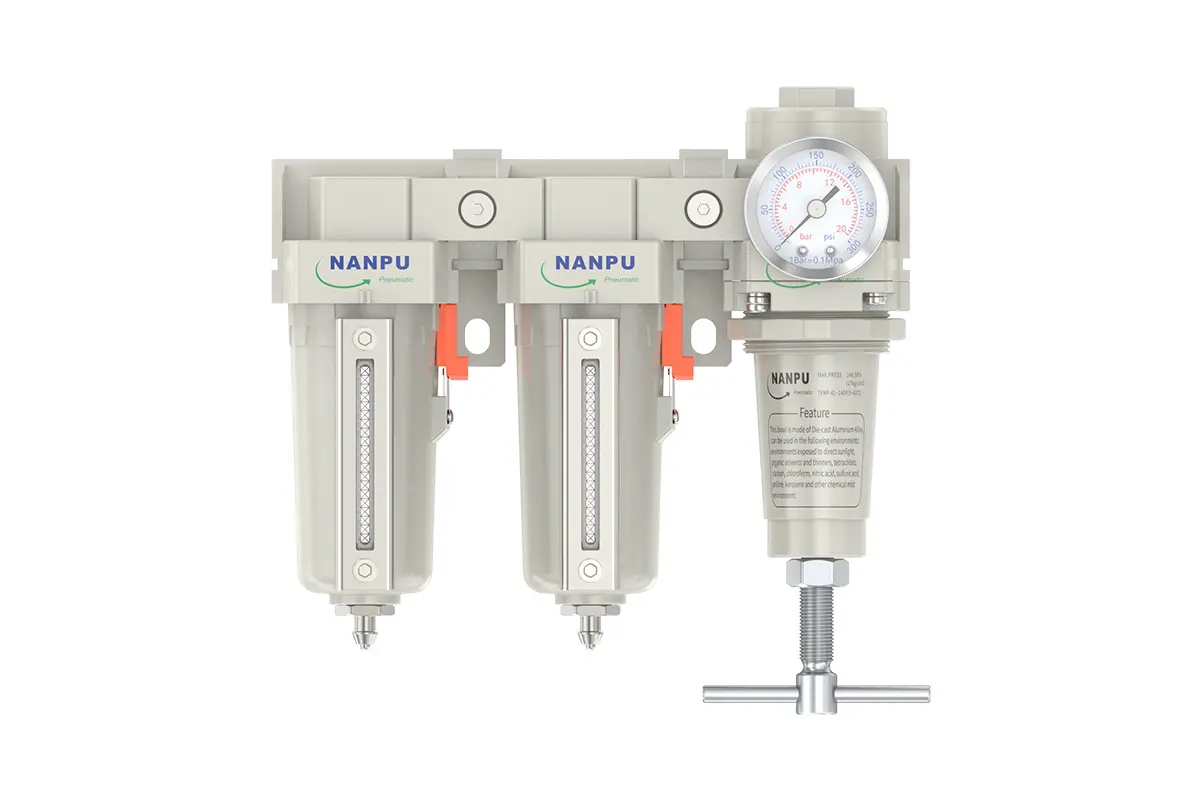
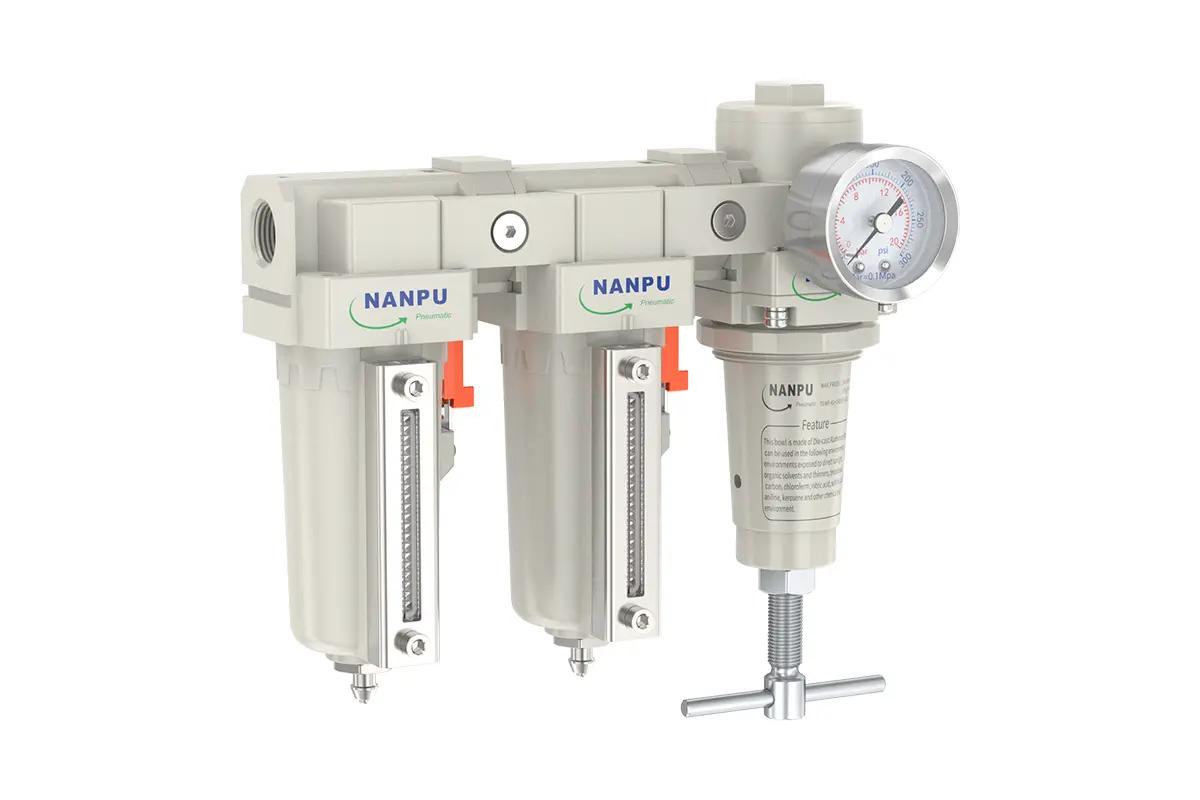
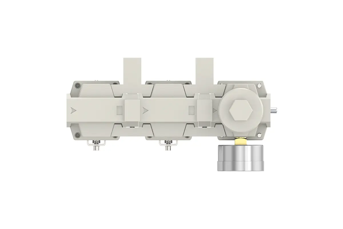
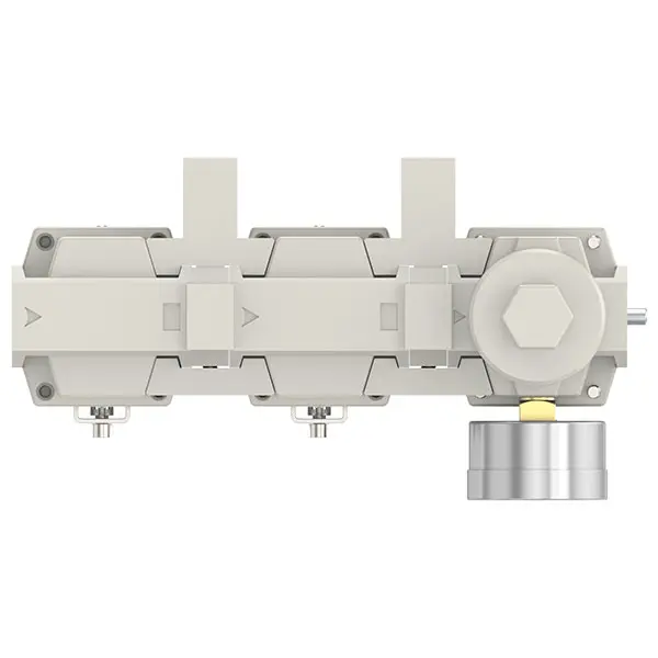
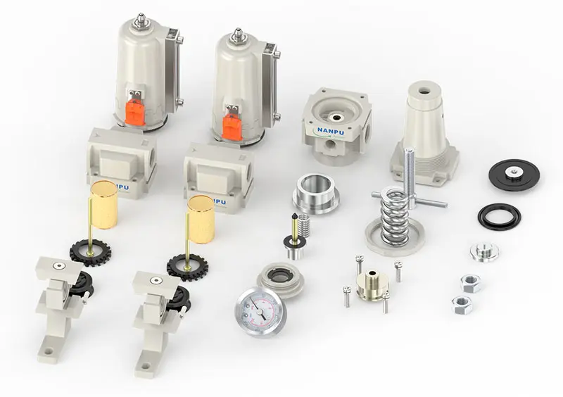
TDFR-02/03 TDFR-04/06 3/8" 1/2" 3/4" Air Drying System
description1
TDFR-02/03 TDFR-04/06 3/8" 1/2" 3/4"
Auto Drain TDFR-02D/03D TDFR-04D/06D 3/8" 1/2" 3/4"
NANPUTDFR-02/03 TDFR-04/06 3/8" 1/2" 3/4" Air Drying System
| TFR | 3000 | MINI | BSP | D |
| Series Number | Port Size | Thread Type | Drainage Method | |
| 3000 | 02:1/4" 03:3/8" | BSP | Blank: Differential Pressure Drain | |
| 4000 | 04:1/2" 06:3/4" | NPT | A: Manual Drain |
NANPUTechnical Specifications
| Max Input Pressure | 2.0MPa (20.39kgf/cm²) 290Psi | |
| Max Operating Pressure | 1.8Mpa (18.35kgf/cm²) 261Psi | |
| Temperature Range | 5-60℃ | |
| Filtration Accuracy | 5µm、40µm、0.01µ | |
| Body Material | Aluminium/Zinc | |
| Bowl Guard | YES | |
| Suggested Oil | Turbine Oil No. 1 ISO-VG32 | |
| Pressure Range | TC3000-4000:0.05~1.8Mpa (0.51~18.35kgf²) | |
| Model Manual Drain | Model Auto Drain | (L/min)Rated Flow Rate |
| TDFR-02 | TDFR-02D | 2000 |
| TDFR-03 | TDFR-03D | 2000 |
| TDFR-04 | TDFR-04D | 4000 |
| TDFR-06 | TDFR-06D | 4500 |
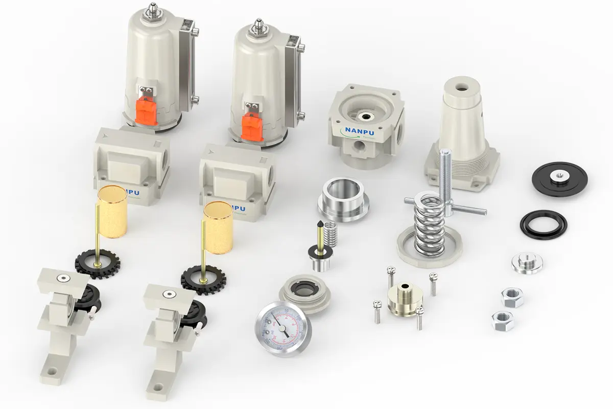
1.Preparation
All calibration components shall comply with the maximum flow rate specification.
Prior to installation, thoroughly clean all ports and fittings to preclude dust contamination of the air pathway.
Confirm that the air flow direction accords with the arrow markings on the product body, and ensure proper matching of port and thread dimensions.
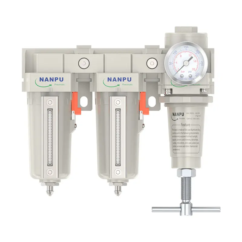
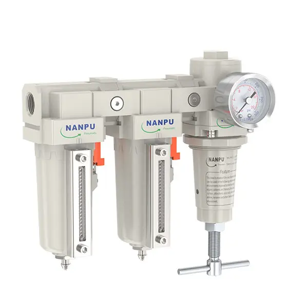
2. Pressure Adjustment
Elevate the pressure gauge knob and rotate it:
A clockwise rotation will gradually raise the pressure, while a counterclockwise rotation will lower it.
Once the target pressure value is reached, stop rotating and firmly press down the knob. Neglecting this step may cause pressure leakage.
3. Dial Reading
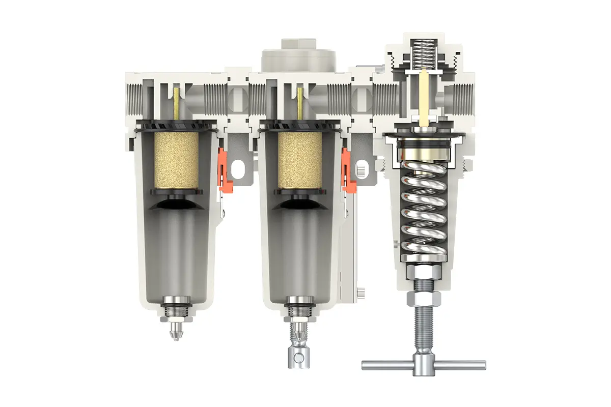
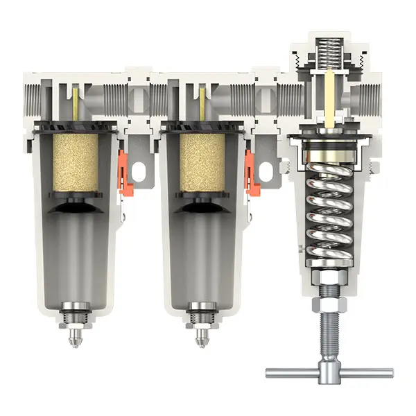
5 - Micron Brass Filter Element: Exhibits superior filtration performance, prolonged service life, and recyclability.
0.5 and 0.01 - Micron Filter Elements: Effectively eliminate micro-contaminants.
The drain valve functions automatically. It opens under pressure-free conditions and closes during air flow. When the water level surpasses the maximum permissible level, immediate drainage is necessary; otherwise, dehumidification efficiency will be severely impaired.
4.Drainage
The drain valve operates automatically. It opens in the absence of pressure and closes when air is flowing. When the water level exceeds the maximum threshold, prompt drainage is essential; failure to do so will result in subpar dehumidification performance. The connector on the drain assembly is designed for attaching an air hose and can be conveniently detached as per operational requirements.
Utilize a wrench to firmly tighten all fittings to prevent leakage. During initial installation, a temporary release of air may occur. This is not a leak; instead, it arises from the pressure differential between the internal system and the external environment, requiring the expulsion of excess air. In such cases, allow adequate time for the system to stabilize, after which it will operate normally.