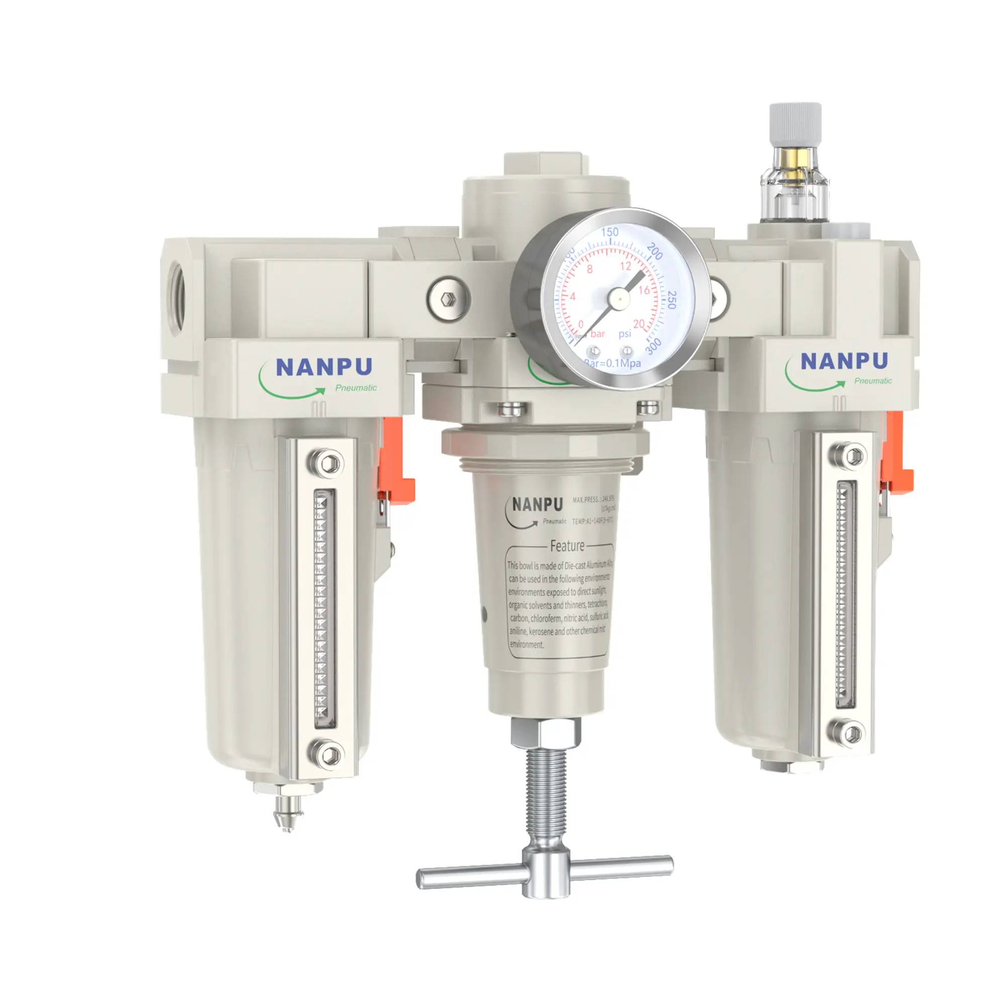
TC Series F.R.L.Combination Air Filter, Regulator & Lubricator
description1
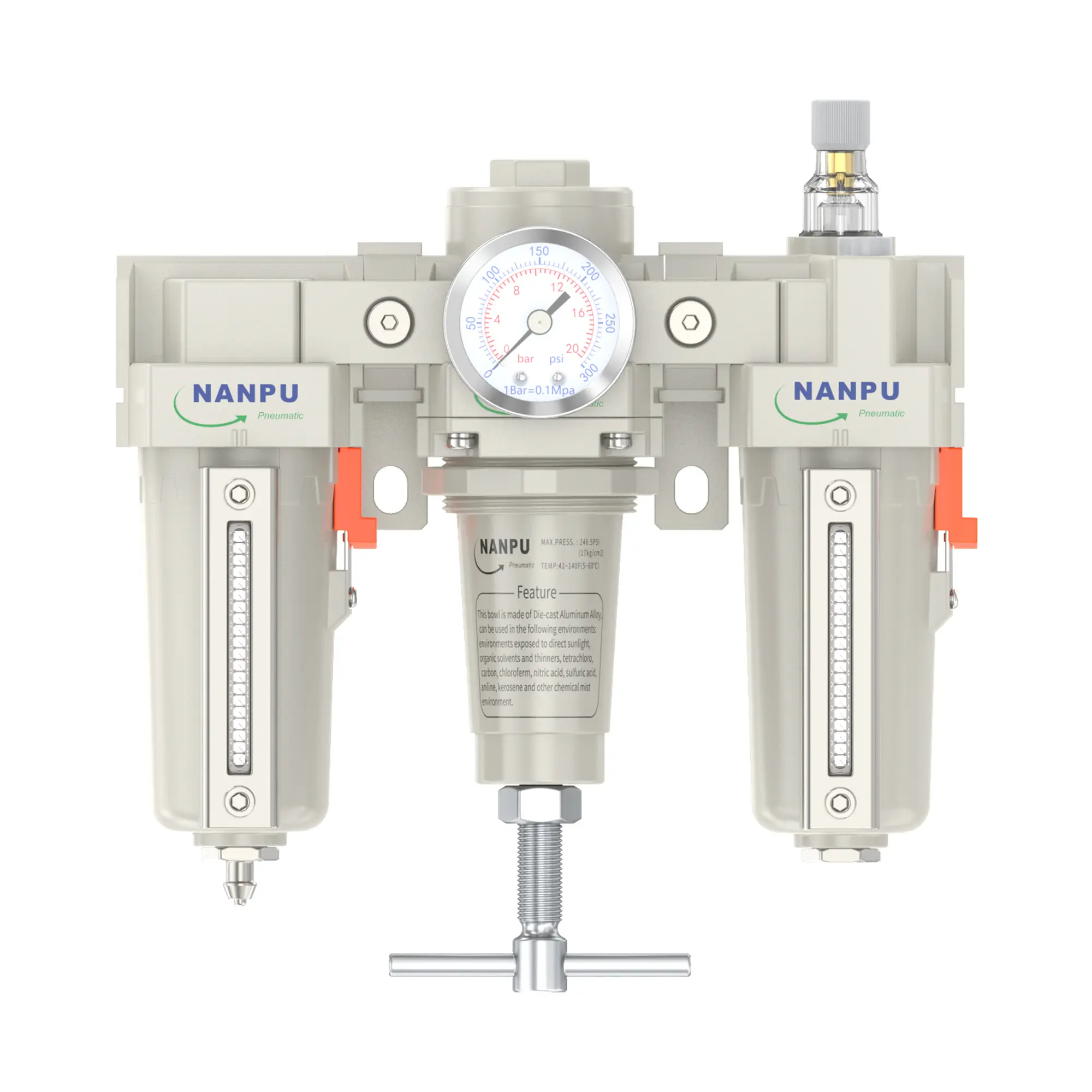
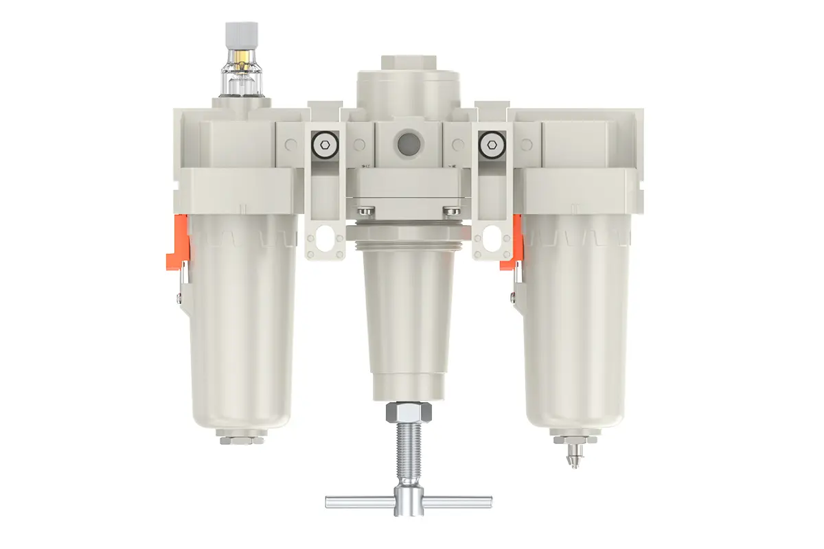
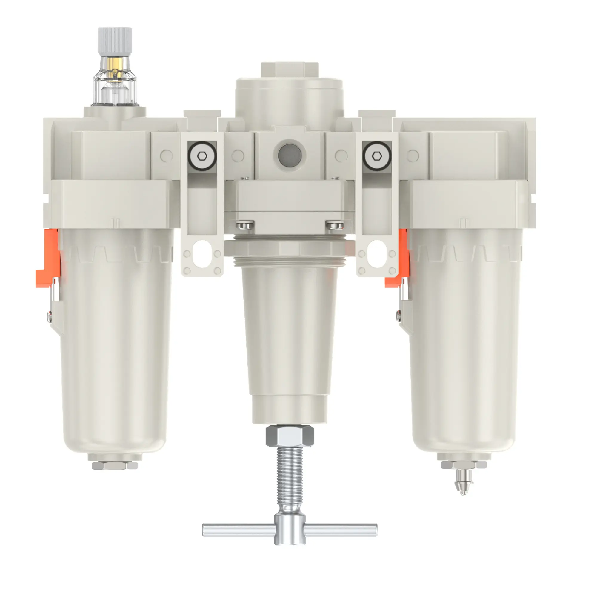
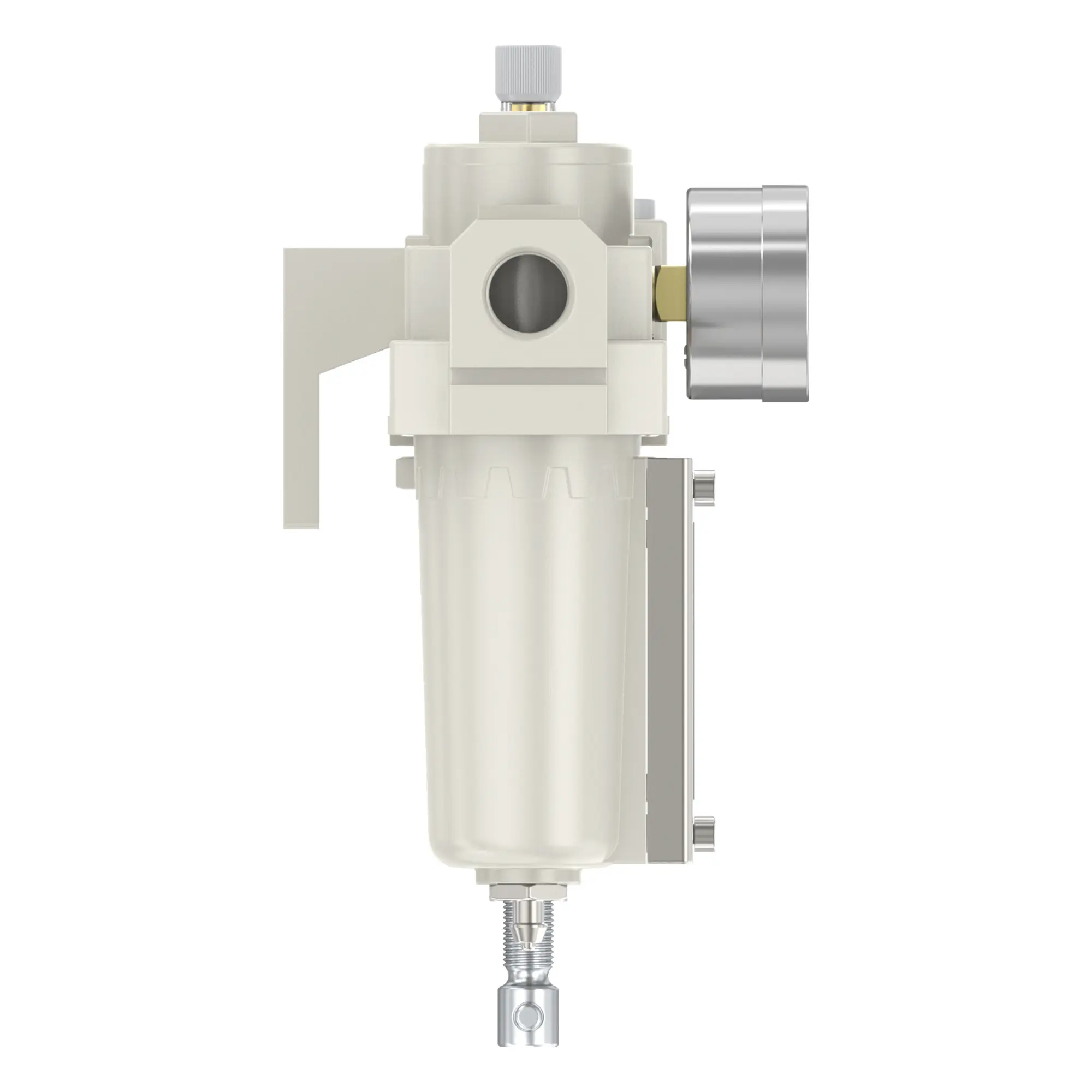
TC3000-02/03 TC4000-04/06 Series F.R.L.Combination Air Filter, Regulator & Lubricator
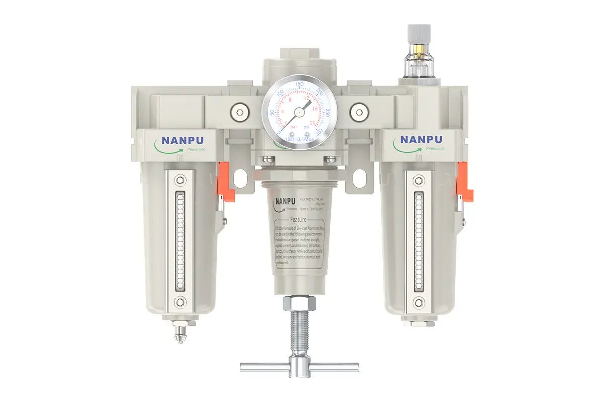
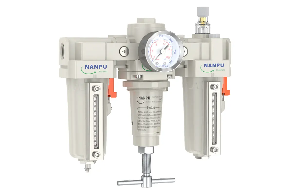
Manual Drain TC3000-02/03 TC4000-04/06 Series F.R.L.Combination Air Filter, Regulator & Lubricator
Auto Drain TC3000-02/03-D TC4000-04/06-D Series F.R.L.Combination Air Filter, Regulator & Lubricator
NANPUTC Series F.R.L.Combination Air Filter, Regulator & Lubricator
| TC | 3000 | MINI | BSP | D |
| Series Number | Port Size | Thread Type | Drainage Method | |
| 3000 | 02:1/4" 03:3/8" | BSP | Blank: Differential Pressure Drain | |
| 4000 | 04:1/2" 06:3/4" | NPT | A: Manual Drain | |
| PT | D: Auto Drain |
NANPUTechnical Specifications
| Technical Specifications | |
| Max Input Pressure | 2.0Mpa{20.39kgf/cm²} 290Psi |
| Max Operating Pressure | 1.8Mpa{18.35kgf/cm²} 261Psi |
| Temperature Range | 5~60℃ |
| Filtration Accuracy | 5μm、40μm |
| Body Material | Aluminium/Zinc |
| Bowl Guard | YES |
| Suggested Oil | Turbine Oil No. 1 ISO-VG32 |
| Pressure Range | TC3000~4000:0.05~1.8Mpa(0.51~18.35kgf) |
| Model | Model | |
| Manual Drain | Auto Drain | (L/min)Rated Flow Rate |
| TC3000-02 | TC3000-02-D | 2000 |
| TC3000-03 | TC3000-03-D | 2000 |
| TC4000-04 | TC4000-04-D | 4000 |
| TC4000-06 | TC4000-06-D | 4500 |
| Bowl Guard | YES | |
| Suggested Oil | Turbine Oil No. 1 ISO-VG32 | |
| Pressure Range | TC3000~4000:0.05~1.8Mpa(0.51~18.35kgf) |
| Product Benefits |
| All Portsize Piggyback Air Filter featuring a standard 5-micron filtration element, along with an integrated Regulator and Lubricator (FRL) assembly. |
| This system is designed to provide dry air, with capabilities for precise pressure regulation and effective air lubrication. |
| The operational temperature range is specified as 41 to 140 degrees Fahrenheit (equivalent to 5 to 60 degrees Celsius). |
NANPUInstallation and Operating
Preparation
All calibration assemblies must comply with maximum flow specifications.
Prior to installation, rigorously purify all ports and fittings to effectively prevent dust ingress into the air passage.
Confirm that the air flow direction corresponds with the arrow markings on the product body and ensure precise alignment of port and thread dimensions.
2. Pressure AdjustmentElevate the pressure gauge knob and initiate rotation. A clockwise turn will effect a steady, uniform pressure increase, while a counterclockwise turn will precipitate a pressure reduction.
Upon reaching the target pressure value, halt rotation and firmly depress the knob to lock it in place. Neglecting this securing procedure may result in pressure leakage complications.