


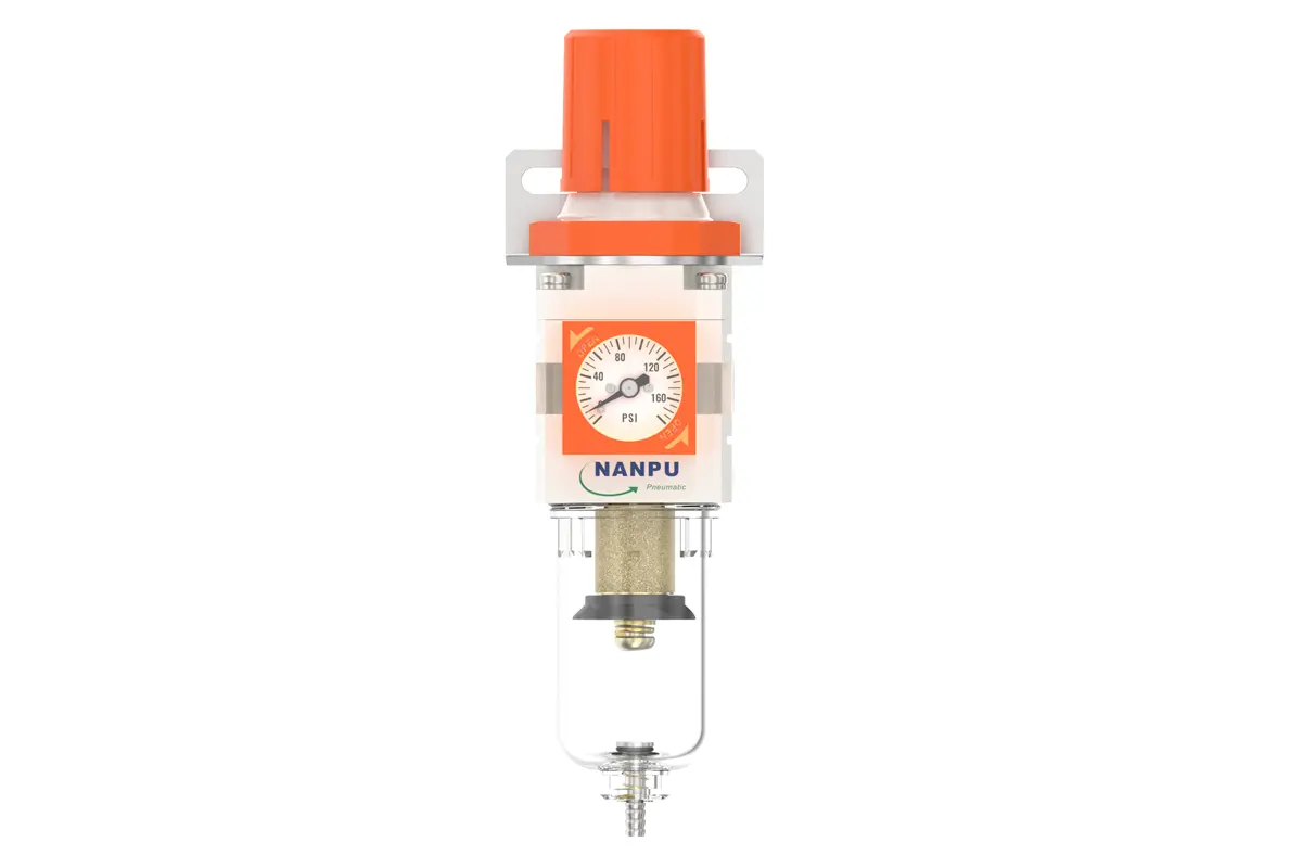
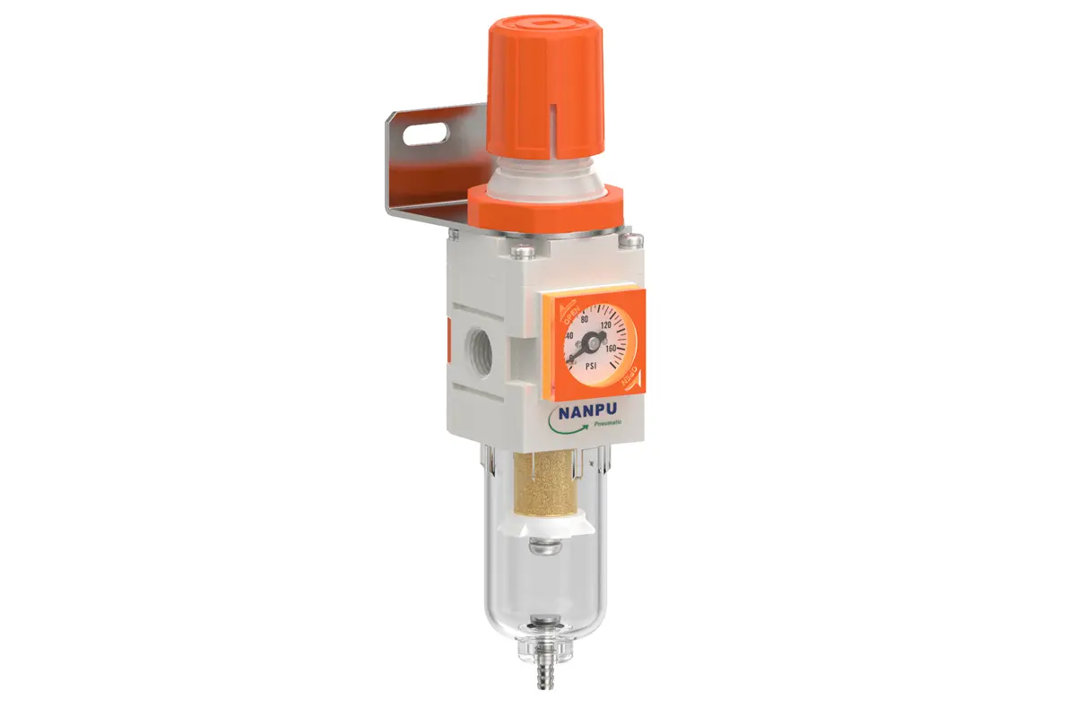
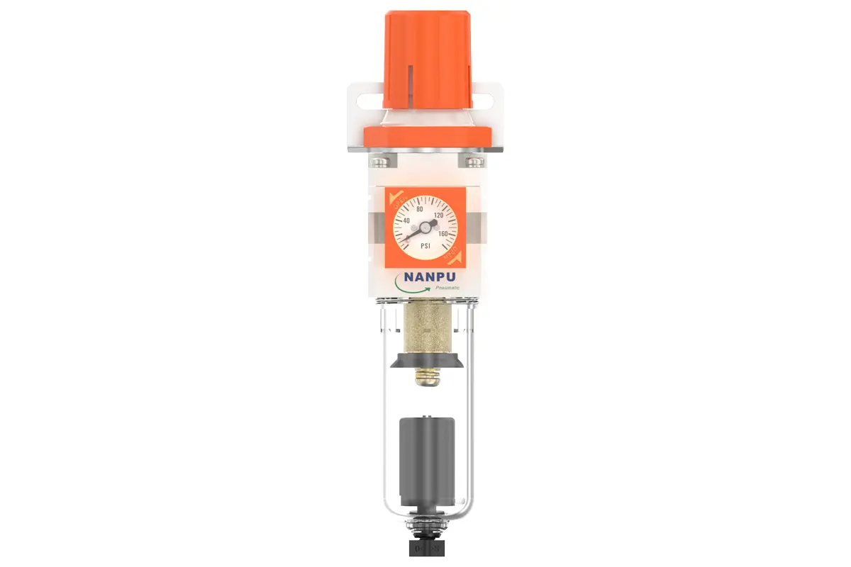
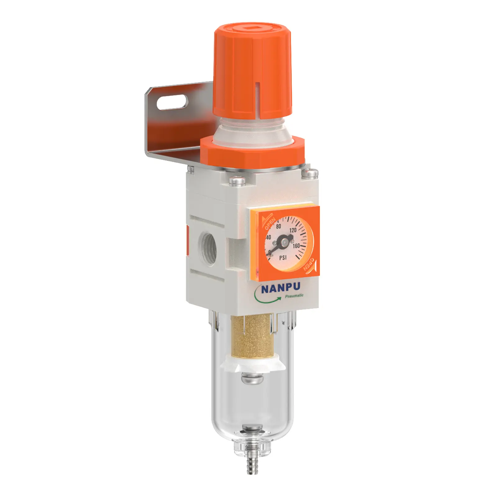
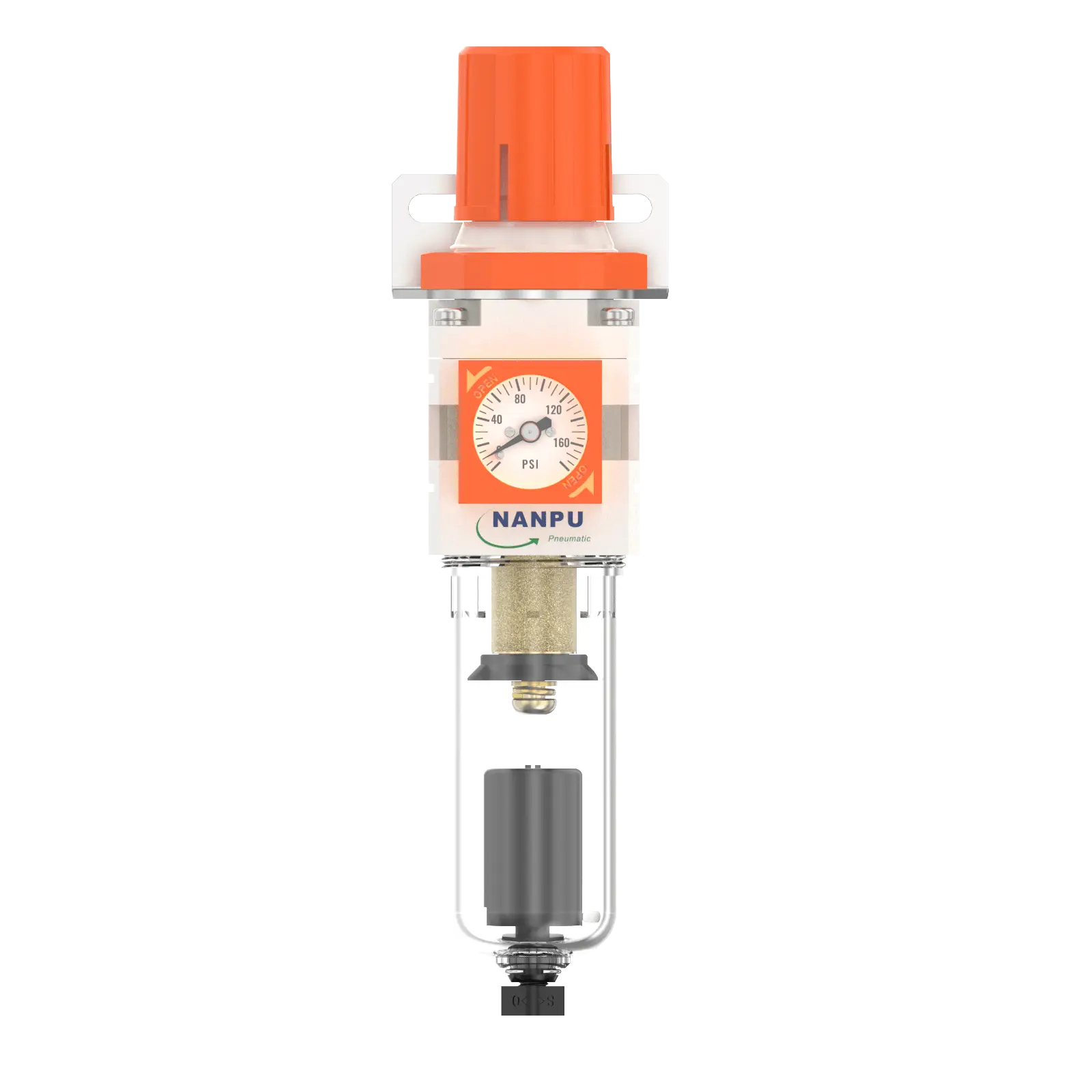
NW2000-02/NW2000-02D AW Filter Regulator with Embedded pressure gauge
description1
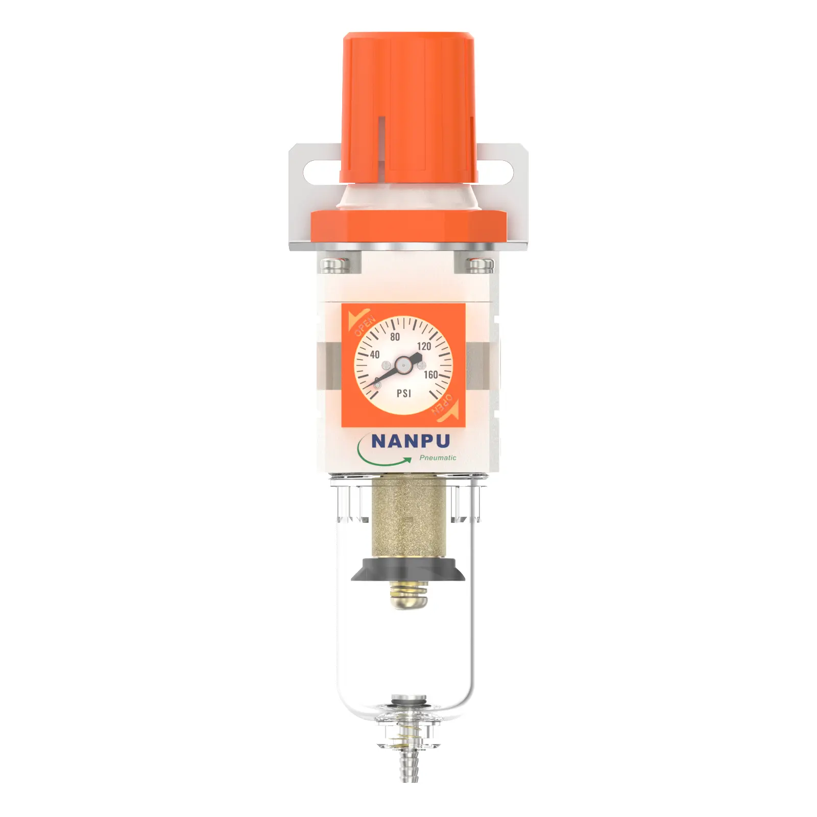
NW2000-02/NW2000-02D AW Filter Regulator with Embedded pressure gauge
Manual Drain NW2000-02 Portsize:1/4" AW Filter Regulator with Embedded pressure gauge
Auto Drain NW2000-02D Portsize:1/4" AW Filter Regulator with Embedded pressure gauge
NANPUNC2010-02/NC2010-02D F.R.L.Combination Air Filter, Regulator & Lubricator with Embedded pressure gauge
| NW | 2000 | 02 | BSP | D |
| Series Number | Body Size | Port Size | Thread Type | Drainage Method |
| 2000 | 02:1/4" | BSP | Blank: Differential Pressure Drain | |
| 3000 | 03:3/8" | NPT | A: Manual Drain | |
| 4000 | 04:1/2" | PT | D: Auto Drain |
NANPUTechnical Specifications
| Technical Specifications | ||
| Max Input Pressure | 1.2Mpa{12.24kgf/cm²} /174.04Psi | |
| Max Operating Pressure | 1.0Mpa{10.2kgf/cm²} /145Psi | |
| Temperature Range | 5~60℃ | |
| Filtration Accuracy | 0.01μm、 5μm、40μm | |
| Bowl Material | Polycarbonate | |
| Bowl Guard | AC2000(None) AC3000~5000(YES) | |
| Pressure Range | AC2000~5000/0.05~0.85Mpa(0.51~8.7kgf/cm² )/0~125Psi | |
| Model | ||
| Manual Drain | Auto Drain | (L/min)Rated Flow Rate |
| NW2000-02 | NW2000-02D | 500 |
| NW3000-02 | NW3010-02D | 2000 |
| NW3000-03 | NW3010-03D | 2000 |
| NW4000-04 | NW4010-04D | 4000 |
| NW4000-06 | NW4010-06D | 4500 |
| Product Benefits | |
| All Portsize Piggyback Air Filter (0.01μm、 5μm、40μm) | |
| Regulator & Filter air dryer system | |
| Temperature Range: 41-140℉ (5-60℃) |
NANPUInstallation and Operating
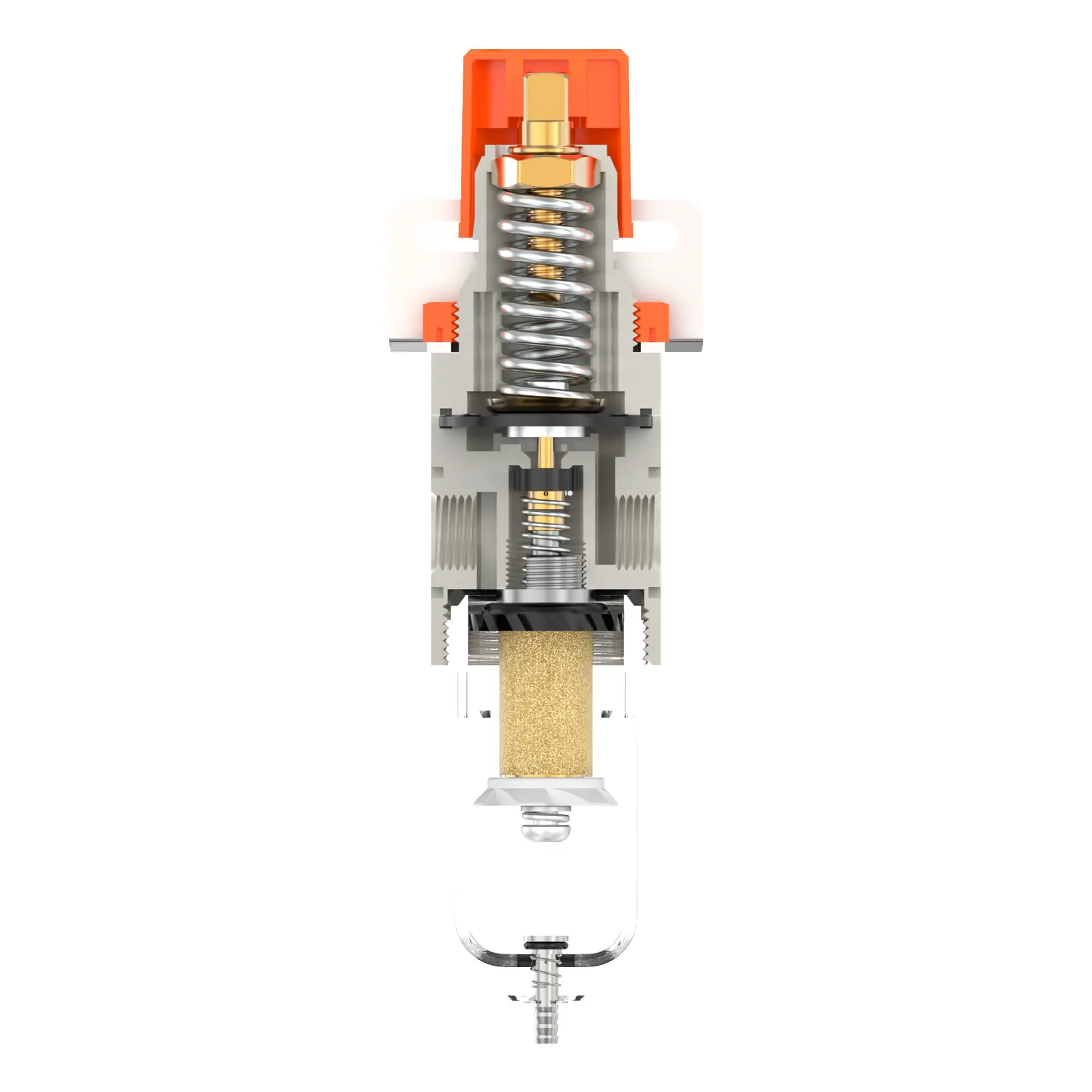
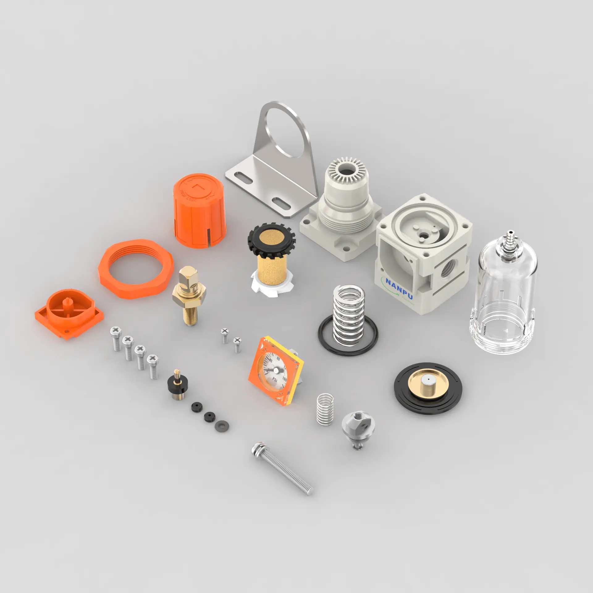
1.Preparation
Each calibration assembly shall adhere to the stipulated maximum flow capacity rating.Prior to installation, the ports and connectors must be thoroughly cleaned to effectively prevent debris from entering the air system.Verify that the airflow direction corresponds with the directional markings on the product housing, and ensure that the port dimensions and thread specifications are properly matched.
2. Pressure Adjustment
Elevate the pressure gauge knob and initiate rotation. Clockwise rotation shall effect a steady and uniform pressure increase, while counterclockwise rotation will result in a proportional pressure decrease. Upon achieving the target pressure value, cease rotation and securely fasten the knob. In the event of improper locking, potential leakage issues may arise, compromising system stability.
3. Dial Reading
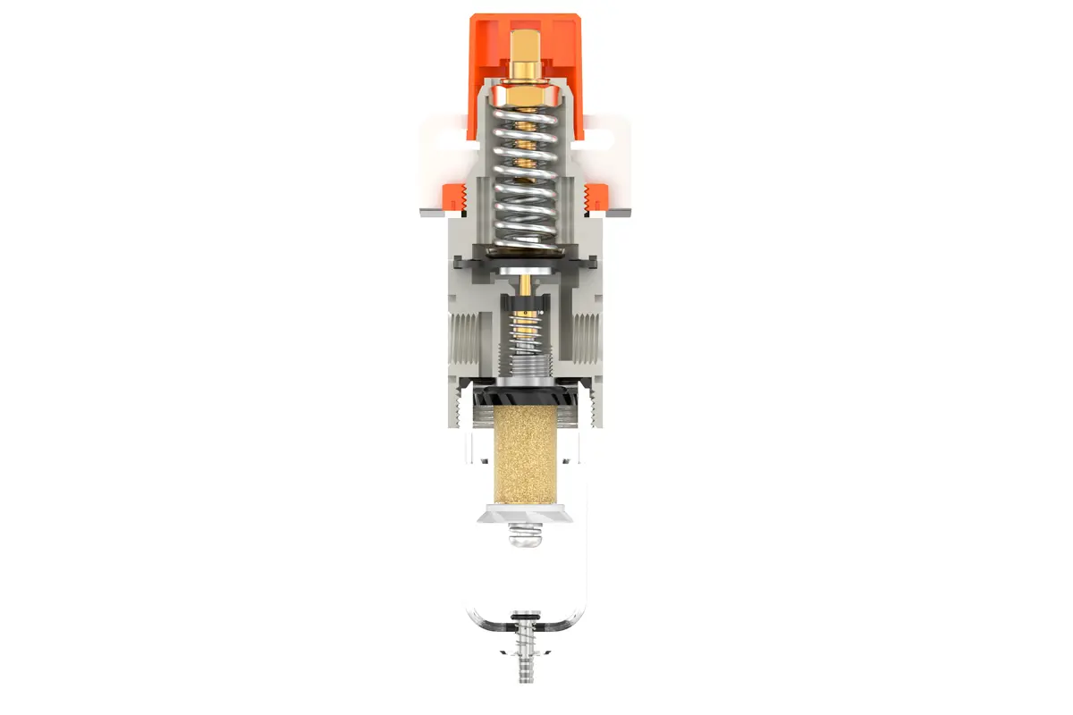
5-μm Brass Filter Element: Delivers exceptional filtration efficiency, superior durability, and multi-cycle reusability.0.5-μm and 0.01-μm Filter Elements: Efficiently trap submicron contaminants.The drain column incorporates a self-actuating mechanism: it opens to discharge contents under zero pressure and closes during air flow. When the water level exceeds the pre-set maximum, immediate drainage is mandatory; otherwise, dehumidification efficiency will significantly deteriorate.
4.Drainage
The drain column incorporates a self-actuating mechanism that opens to expel accumulated matter under zero-pressure conditions and seals tightly during airflow. When the water level reaches or exceeds the allowable maximum, immediate drainage is imperative; failure to do so will result in diminished dehumidification efficiency.
The drain head connector serves as a standardized mounting point for air hoses and may be disassembled per specific operational requirements or system configurations.
Utilize a calibrated torque wrench to tighten the connectors to the specified torque value to prevent any leakage. During initial system installation, an air release may occur, which is not a leak but rather a result of the pressure differential between the interior and exterior, necessitating the expulsion of excess air. In such cases, allow the system to stabilize for an appropriate duration, after which it will operate as intended.