


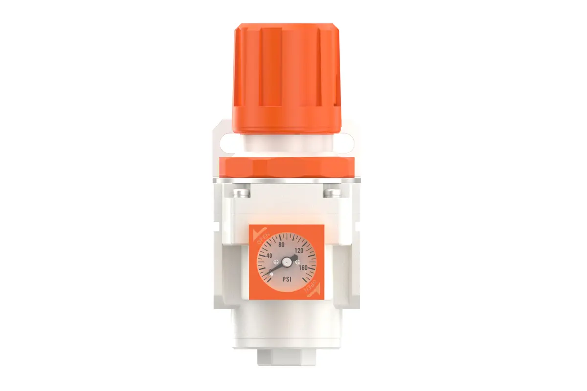
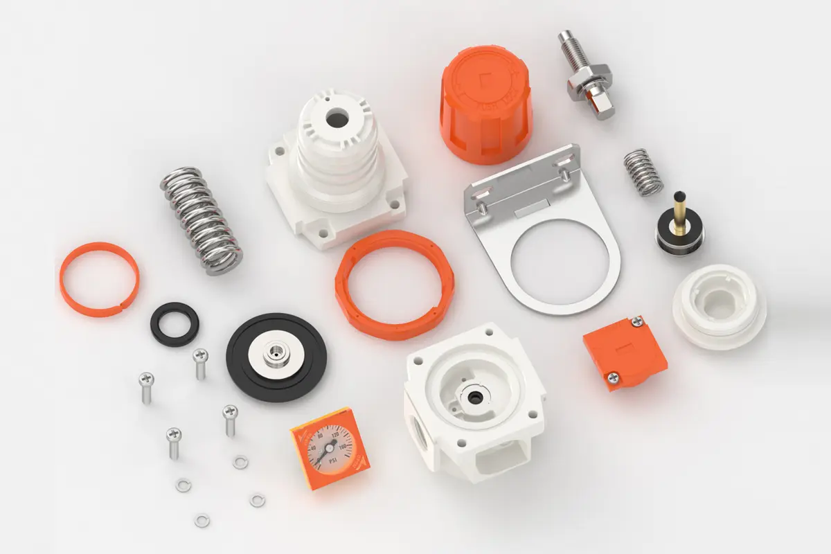
NR3000-03 3/8" NR4000-04 1/2" AR Air Regulator with Embedded pressure gauge
description1
NR2000-02 1/4" AR Air Regulator with Embedded pressure gauge
NR2000-02 1/4" AR Air Regulator with Embedded pressure gauge
NANPU NR3000-03 3/8" NR4000-04 1/2" AR Air Regulator with Embedded pressure gauge
| NR | 3000 | 03 | BSP |
| Series Number | Body Size | Port Size | Thread Type |
| 2000 | 02:1/4" | BSP | |
| 3000 | 03:3/8" | NPT | |
| 4000 | 04:1/2" | PT |
NANPUTechnical Specifications
| Technical Specifications | |
| Max Input Pressure | 1.2Mpa{12.24kgf/cm²} /174.04Psi |
| Max Operating Pressure | 1.0Mpa{10.2kgf/cm²} /145Psi |
| Temperature Range | 5~60℃ |
| Pressure Range | AC2000~5000/0.05~0.85Mpa(0.51~8.7kgf/cm² )/0~125Psi |
| Model | Specification |
| NR2000-02 | 500 |
| NR3000-02 | 2000 |
| NR3000-03 | 2000 |
| NR4000-04 | 4000 |
| NR4000-06 | 4500 |
| Product Benefits |
| The assembly of all calibration shall meet the maximum flow requirement. Please clean the port and fitting before installation, it will effectively avoid bring dust to the air path. Pay attention to direction of air flow and arrow pointing on product body if correct, minding port and thread size if match. |
NANPUPreparation
All calibration assemblies shall strictly adhere to the maximum flow rate specifications outlined in the technical documentation. Such adherence is critical to safeguarding the system's optimal performance and operational reliability.
Prior to installation, it is imperative to meticulously cleanse all ports and fittings using appropriate cleaning agents and standardized protocols. This rigorous cleansing process effectively prevents the ingress of dust, debris, and other contaminants into the air passage, thereby preserving the compressed air system's structural integrity and operational efficiency.
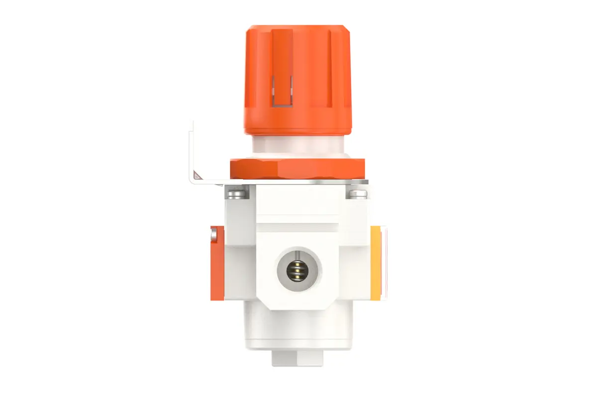
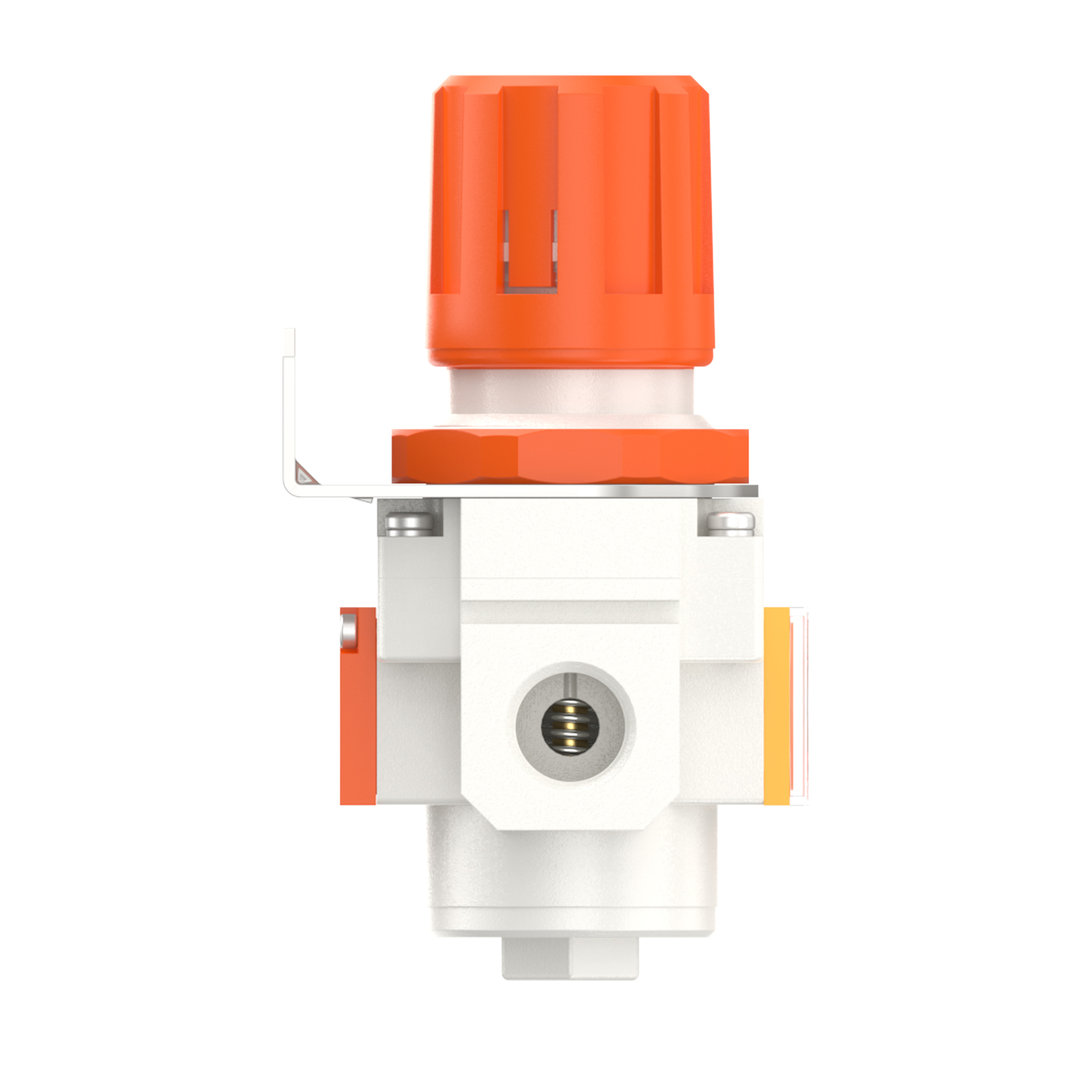
During installation, meticulous attention must be paid to verifying that the air flow direction aligns precisely with the arrow indicators on the product housing. Furthermore, it is essential to confirm that the port and thread dimensions are accurately compatible with the mating components. This thorough verification of dimensions and flow direction is indispensable for mitigating potential installation discrepancies that could lead to system malfunctions or operational inefficiencies.

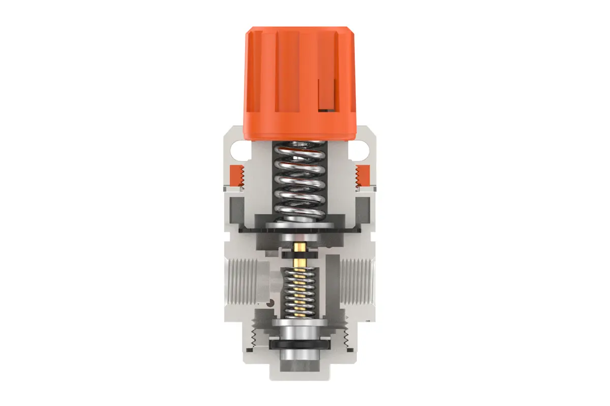
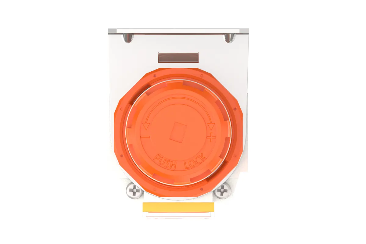
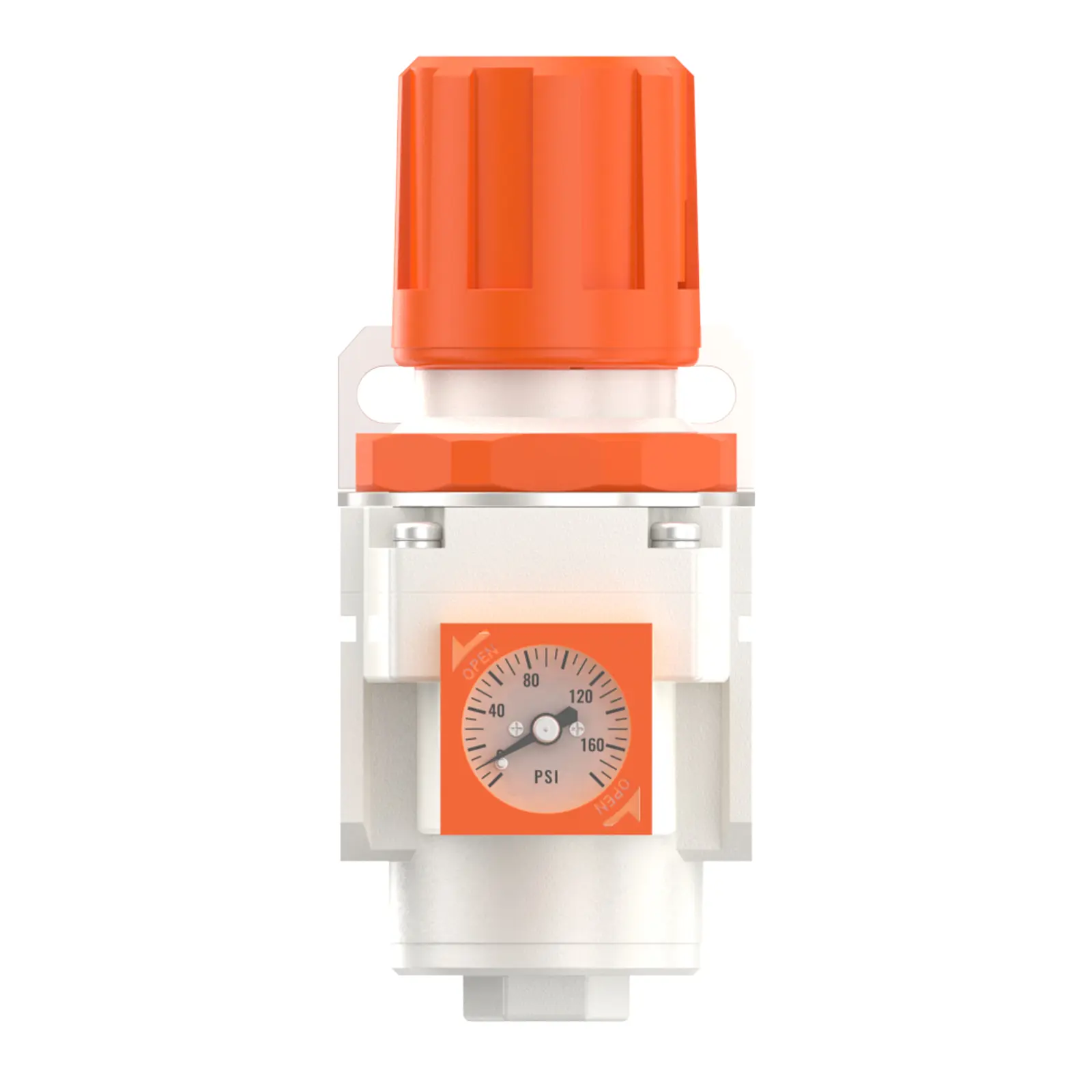
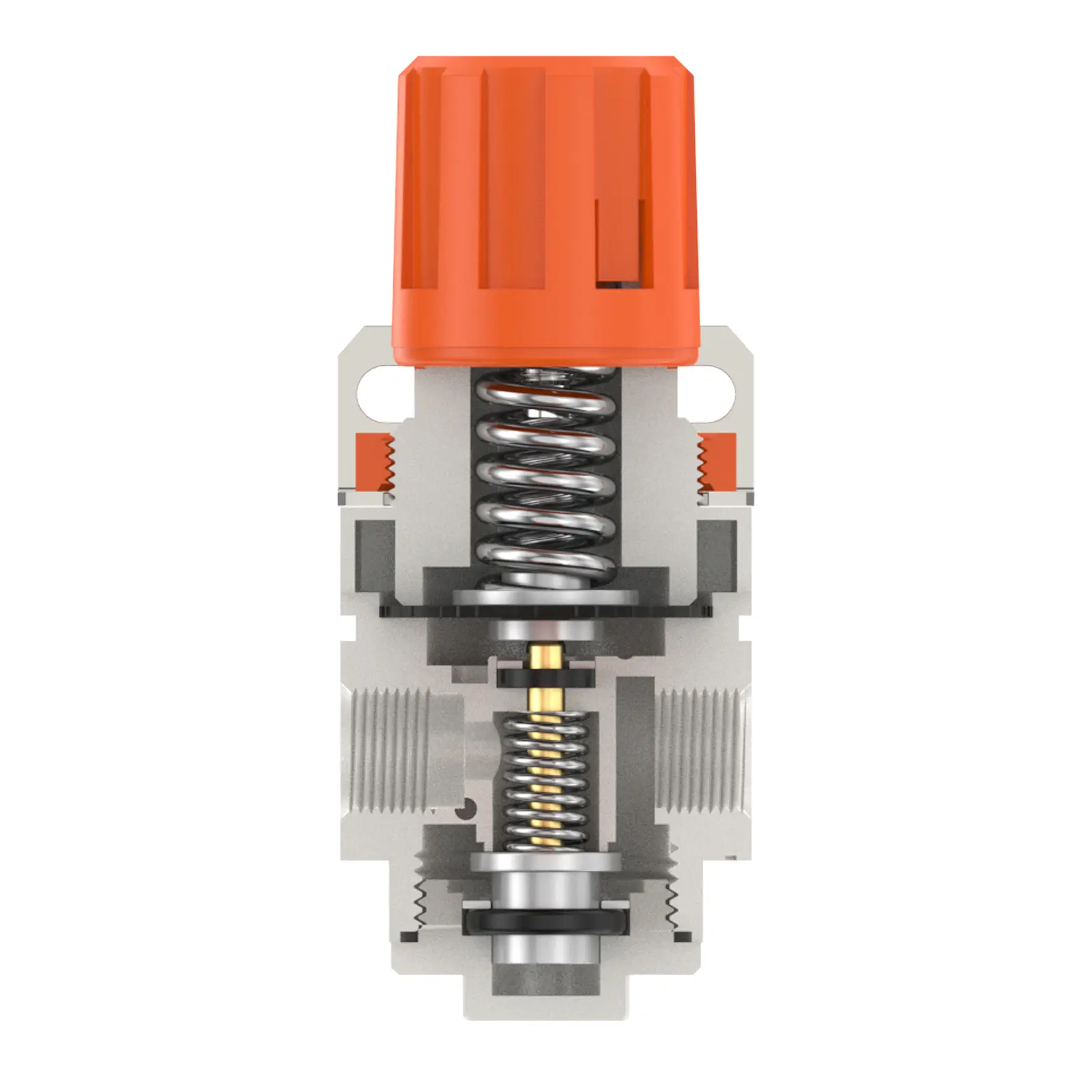
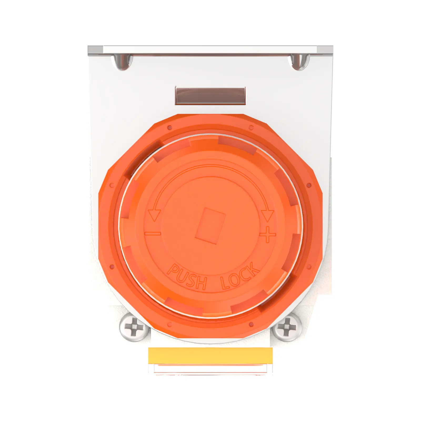
To adjust the pressure, initially, lift the pressure adjustment knob to the unlocked position. Subsequently, rotate the knob to modify the pressure settings. A clockwise rotation will induce a gradual, consistent pressure elevation, whereas a counterclockwise rotation will trigger a steady pressure reduction.
It is critical to monitor the pressure gauge closely and cease rotation once the target pressure value is achieved. Upon reaching the required pressure level, firmly depress the knob to lock and secure the setting. Insufficient locking of the knob may result in a compromised seal, which could potentially lead to leakage issues that impair the system's performance and safety. During operation, conduct regular inspections of the locked knob to ensure the pressure remains stable and within the specified range.
Ensure that the pressure gauge is securely and correctly affixed to the main body using appropriate installation tools and methodologies, while complying with specified torque parameters to prevent potential leakage or displacement. During the pressure adjustment process, closely monitor the pressure gauge to verify that readings exhibit smooth, consistent elevation and reduction, without erratic fluctuations or seizure. Any anomalous behavior in gauge readings may indicate issues such as internal obstructions, component damage, or calibration deviations—these scenarios shall be promptly investigated and addressed to sustain the accuracy and reliability of the pressure monitoring system.