


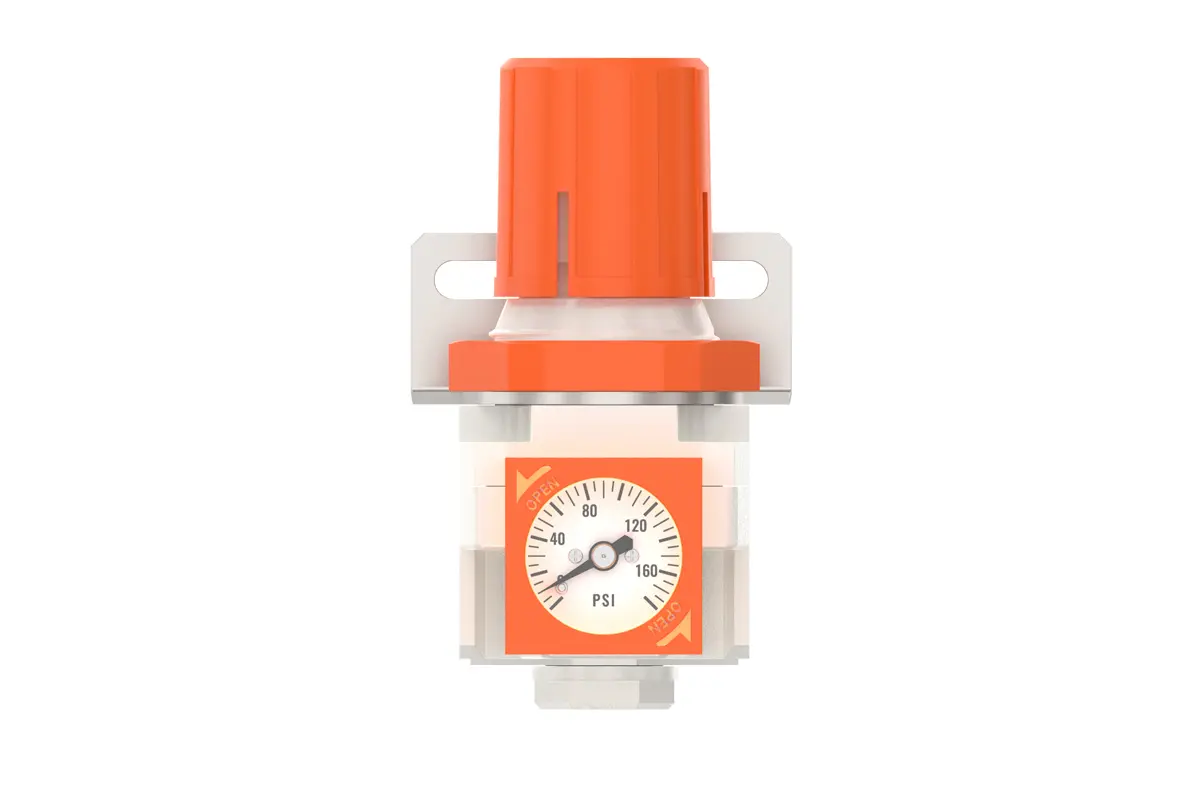
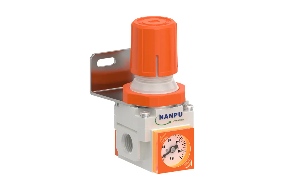
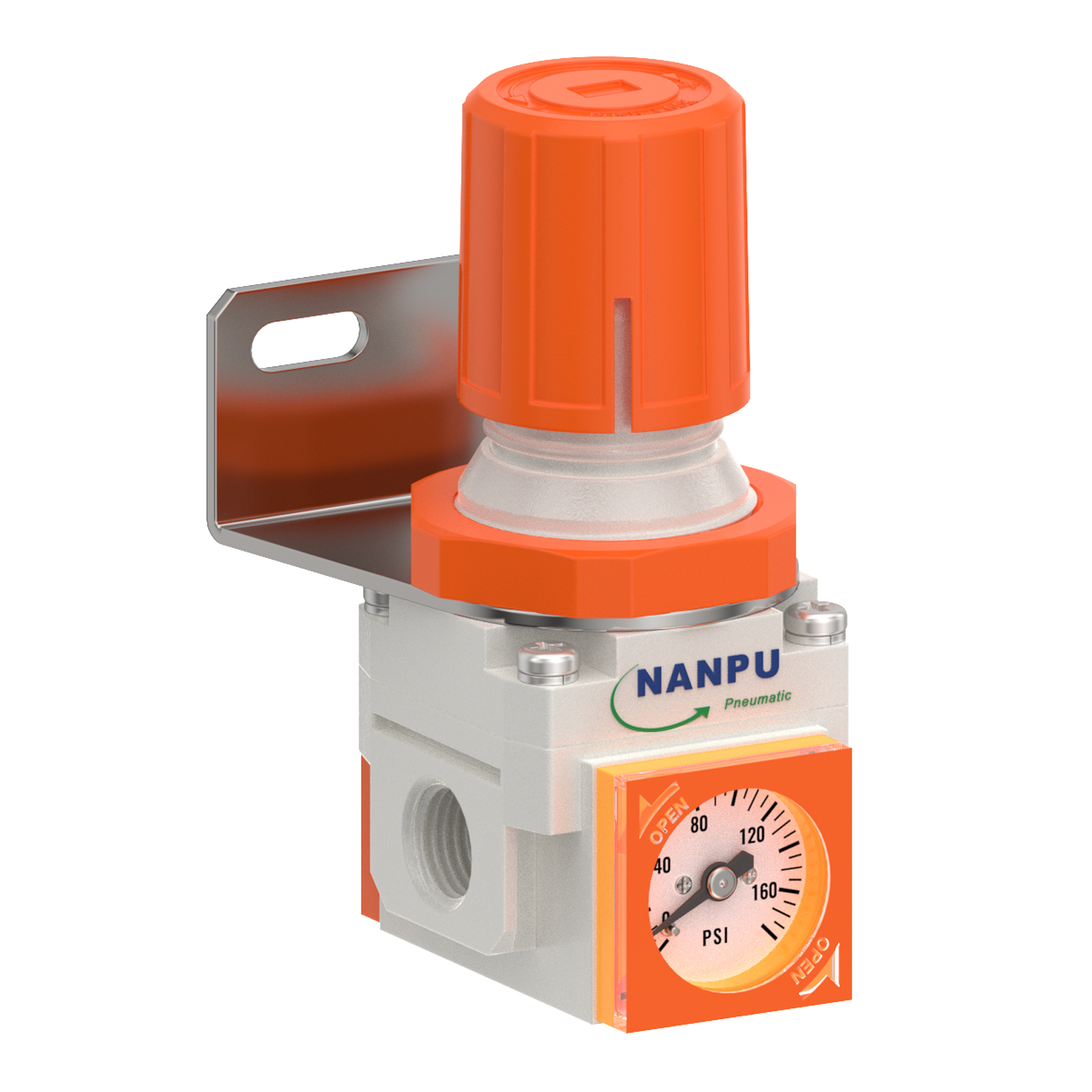
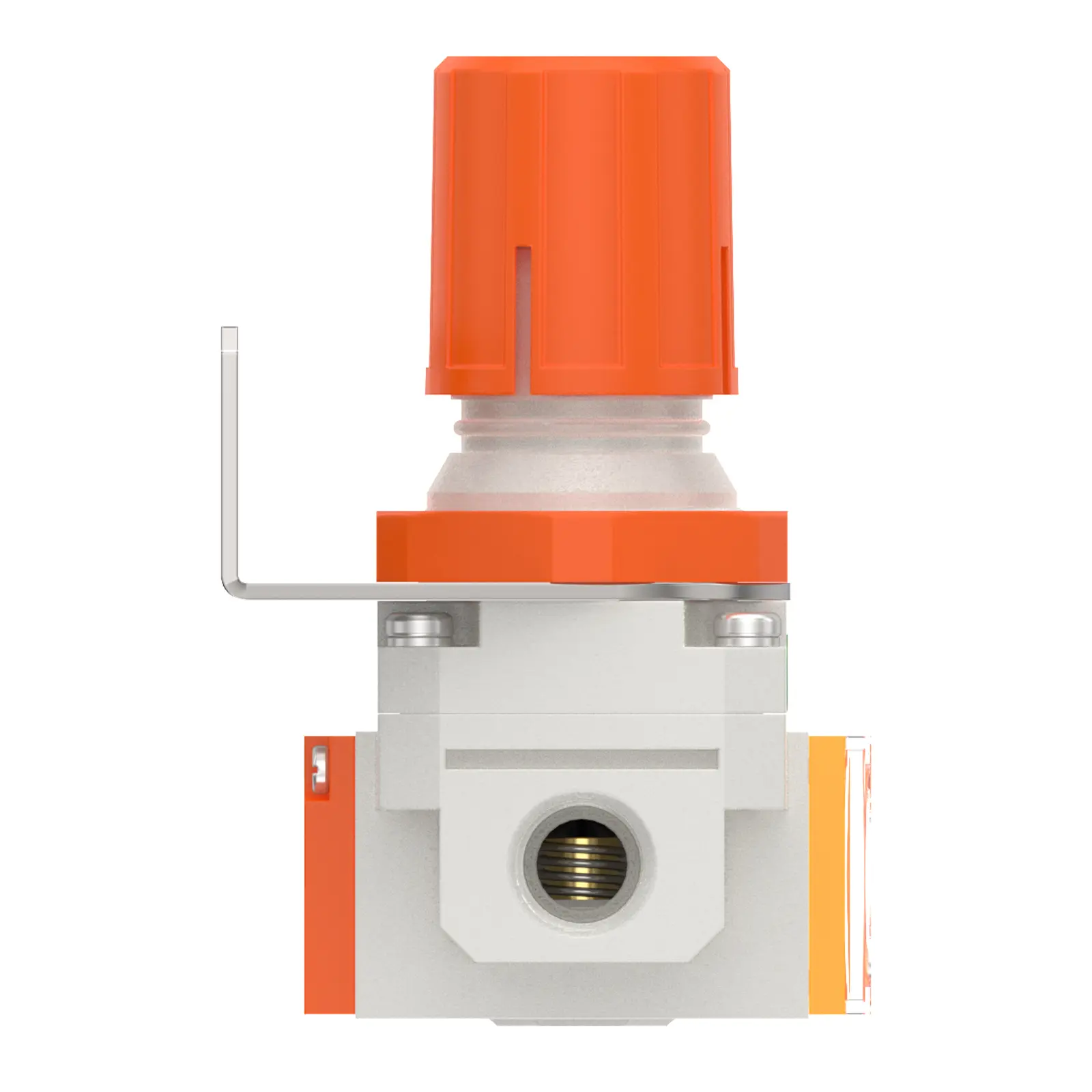
NR2000-02 1/4" AR Air Regulator with Embedded pressure gauge
description1
NR2000-02 1/4" AR Air Regulator with Embedded pressure gauge
NR2000-02 1/4" AR Air Regulator with Embedded pressure gauge
NANPUNR2000-02 1/4" AR Air Regulator with Embedded pressure gauge
| NR | 3000 | 03 | BSP |
| Series Number | Body Size | Port Size | Thread Type |
| 2000 | 02:1/4" | BSP | |
| 3000 | 03:3/8" | NPT | |
| 4000 | 04:1/2" | PT |
NANPUTechnical Specifications
| Technical Specifications | |
| Max Input Pressure | 1.2Mpa{12.24kgf/cm²} /174.04Psi |
| Max Operating Pressure | 1.0Mpa{10.2kgf/cm²} /145Psi |
| Temperature Range | 5~60℃ |
| Pressure Range | AC2000~5000/0.05~0.85Mpa(0.51~8.7kgf/cm² )/0~125Psi |
| Model | Specification |
| NR2000-02 | 500 |
| NR3000-02 | 2000 |
| NR3000-03 | 2000 |
| NR4000-04 | 4000 |
| NR4000-06 | 4500 |
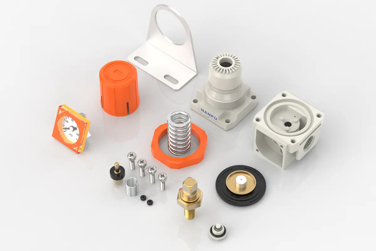
| Product Benefits |
| The assembly of all calibration shall meet the maximum flow requirement. Please clean the port and fitting before installation, it will effectively avoid bring dust to the air path. Pay attention to direction of air flow and arrow pointing on product body if correct, minding port and thread size if match. |
NANPUPreparation
All calibration assemblies shall strictly comply with the maximum flow rate requirements stipulated in the technical documentation. Such compliance is critical to ensuring the optimal performance and reliability of the system.
Prior to installation, it is imperative to meticulously clean all ports and fittings by utilizing suitable cleaning agents and standardized procedures. This thorough cleaning process effectively prevents dust, debris, and other contaminants from entering the air passage, thereby preserving the integrity and operational efficiency of the compressed air system.
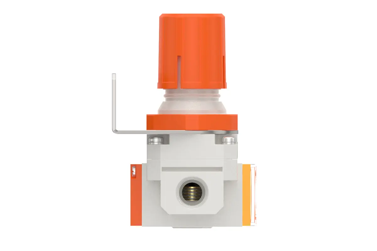
During the installation process, careful attention must be paid to verifying that the air flow direction is in precise alignment with the arrow indicators on the product body. Furthermore, it is essential to ensure that the port and thread dimensions are accurately compatible with the corresponding components. This meticulous verification of dimensions and flow direction is indispensable for avoiding potential installation errors that may result in system malfunctions or operational inefficiencies.
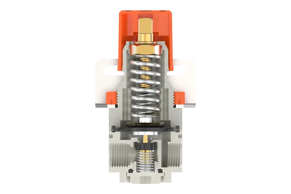
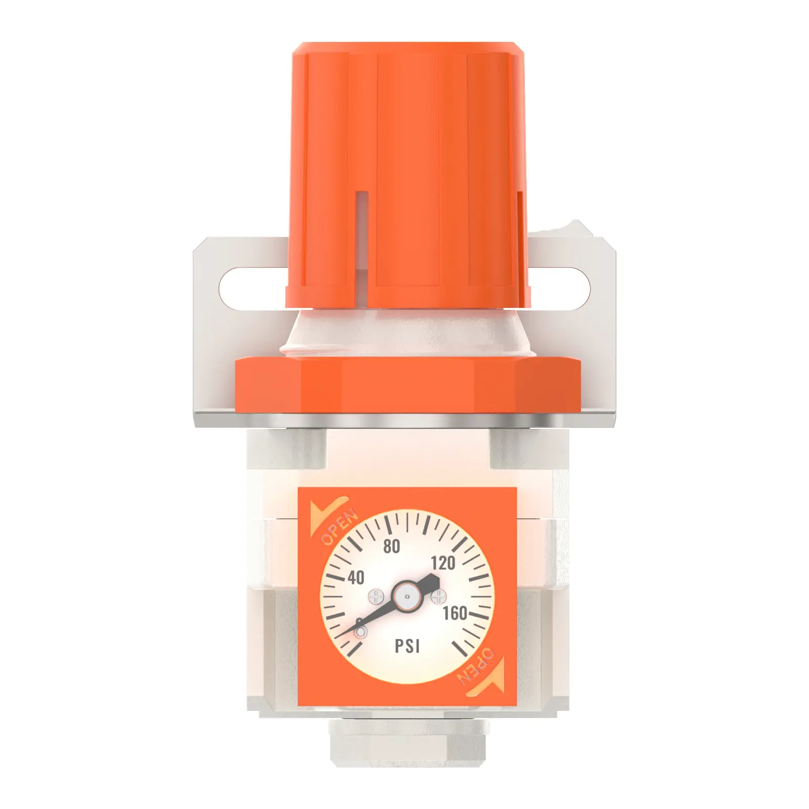
To adjust the pressure, initially, lift the pressure adjustment knob to the unlocked position. Subsequently, rotate the knob to modify the pressure settings. A clockwise rotation will induce a gradual and consistent pressure increase, whereas a counterclockwise rotation will trigger a steady pressure decrease.
It is critical to monitor the pressure gauge closely and terminate rotation once the target pressure value is attained. Upon reaching the required pressure level, firmly depress the knob to lock and secure the setting. Inadequate locking of the knob may result in a compromised seal, which could potentially lead to leakage problems that undermine the system's performance and safety. During operation, conduct regular inspections of the locked knob to ensure the pressure remains stable and within the specified range.
Ensure that the pressure gauge is securely and correctly mounted on the main body by utilizing appropriate installation tools and methodologies, while adhering to the specified torque requirements to preclude potential leakage or displacement. During the pressure adjustment process, closely monitor the pressure gauge to confirm that the readings increase and decrease in a smooth, consistent manner, free from erratic fluctuations or jamming. Any abnormal behavior in the gauge readings may indicate issues such as internal blockages, damaged components, or improper calibration—these circumstances shall be promptly investigated and resolved to maintain the accuracy and reliability of the pressure monitoring system.