


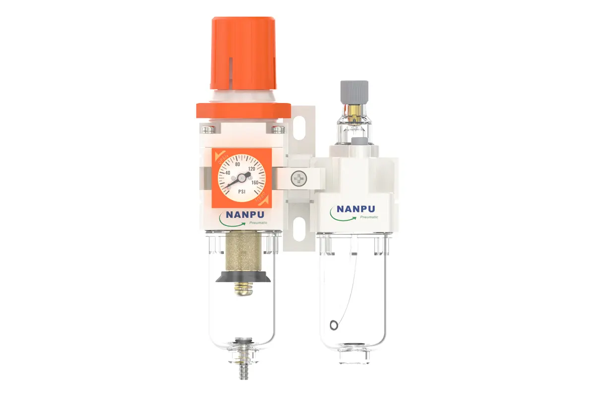
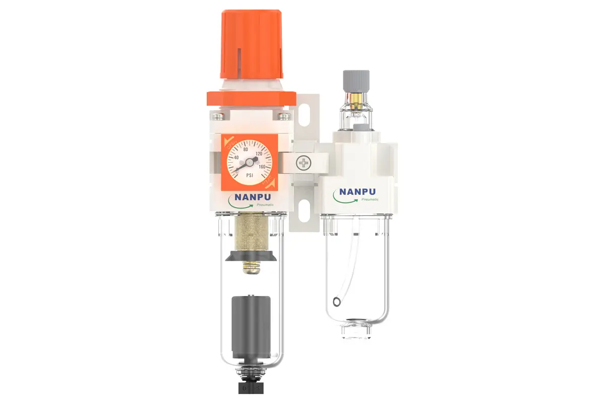
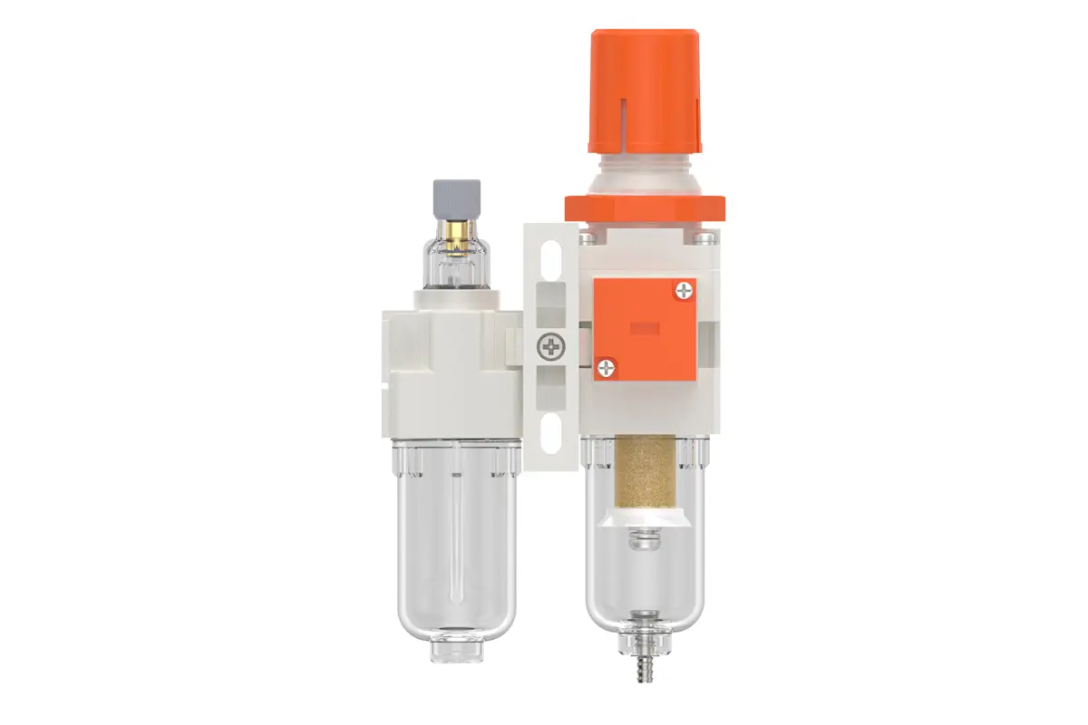

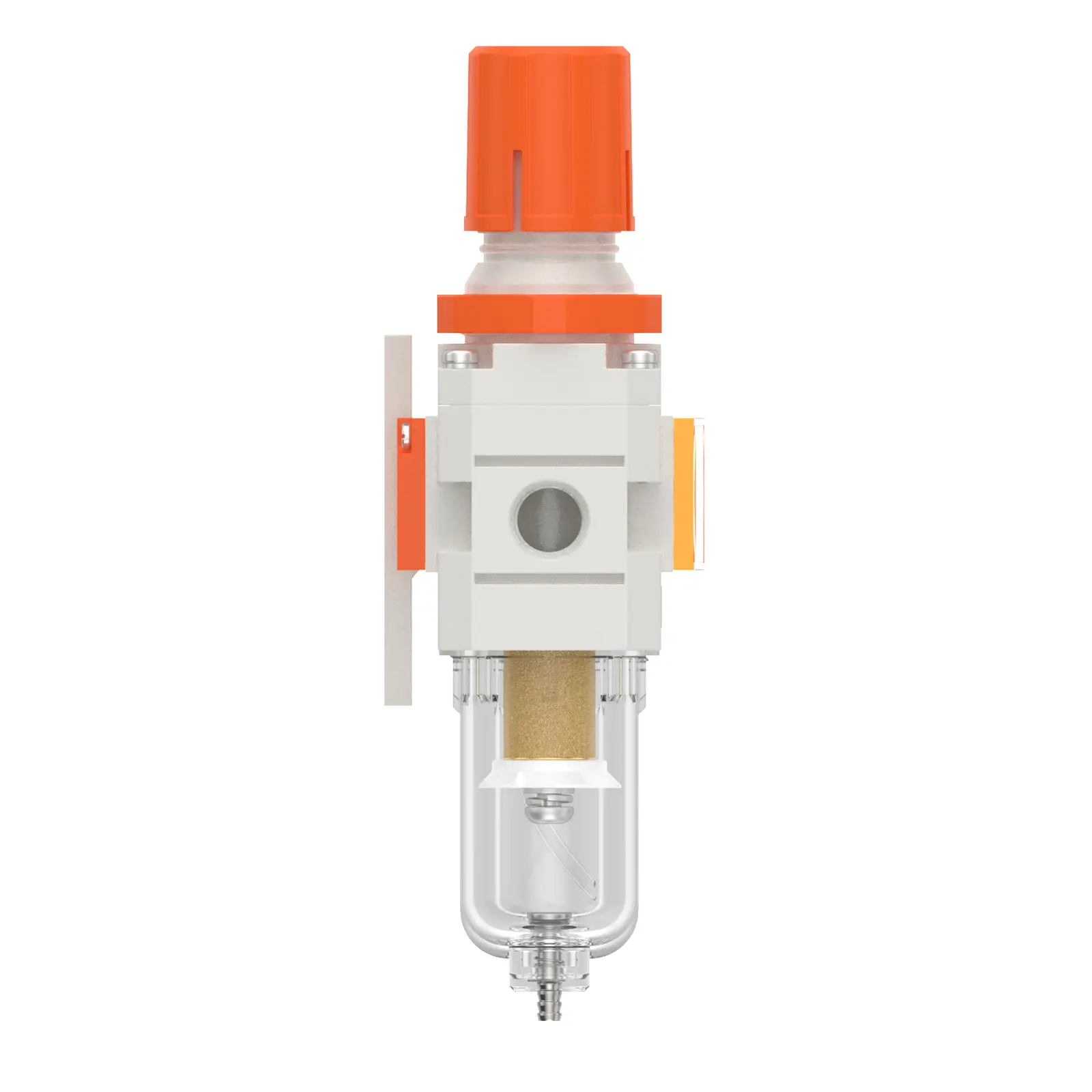
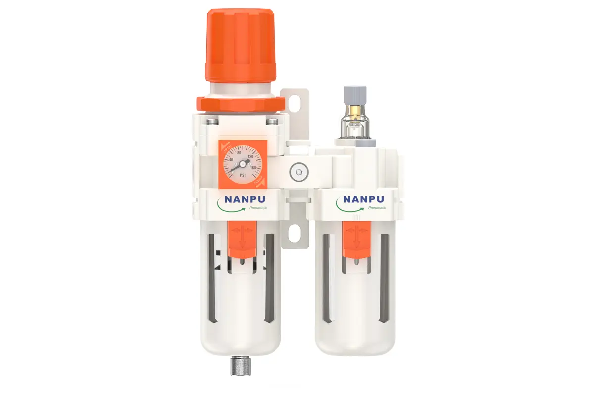
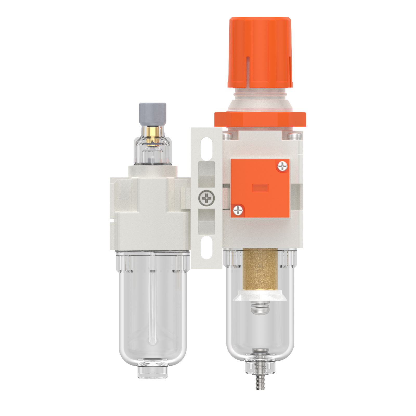
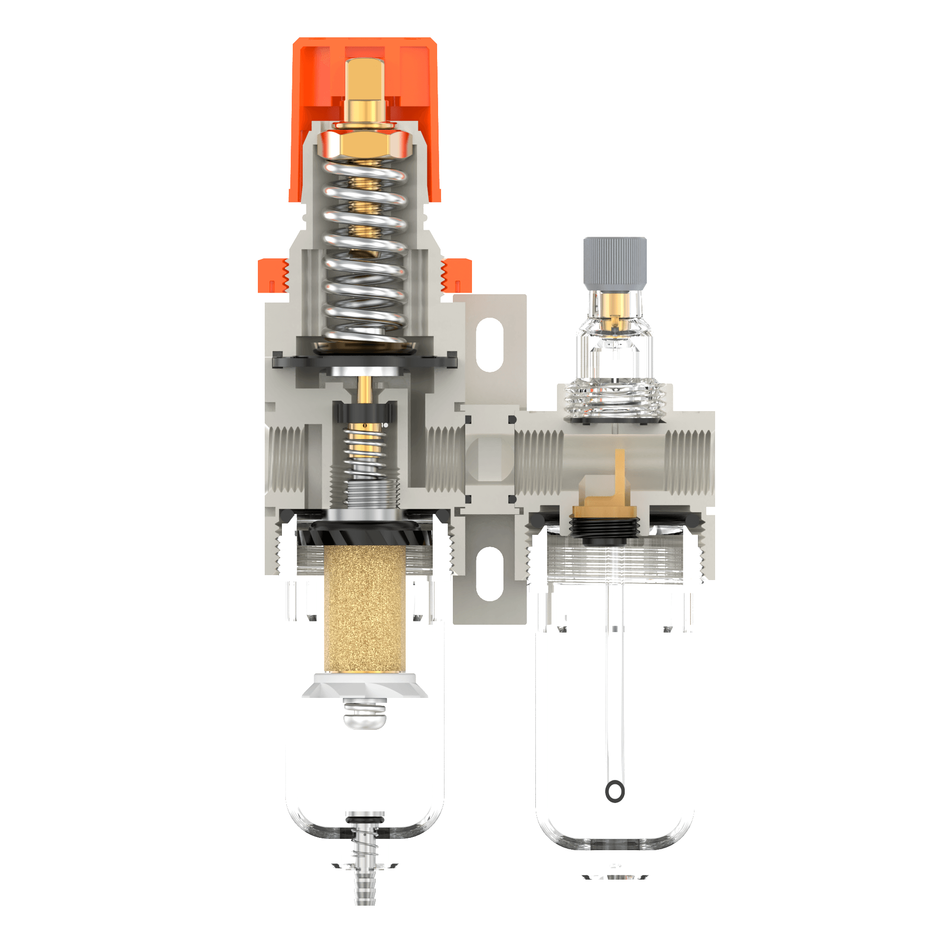
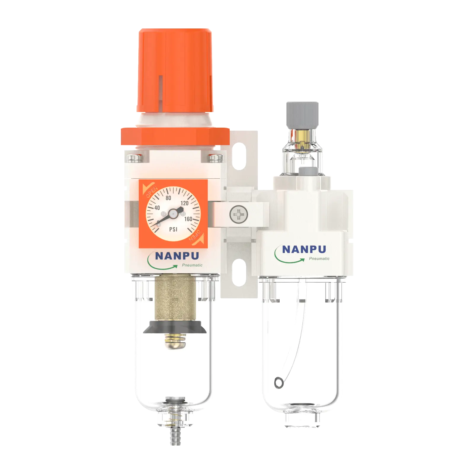
NC2010-02/NC2010-02D F.R.L.Combination Air Filter, Regulator & Lubricator with Embedded pressure gauge
description1
AC2010-02/AC2010-02D
Manual Drain NC2010-02 Portsize:1/4" F.R.L.Combination Air Filter, Regulator & Lubricator
Auto Drain NC2010-02D Portsize:1/4" F.R.L.Combination Air Filter, Regulator & Lubricator
NANPUNC2010-02/NC2010-02D F.R.L.Combination Air Filter, Regulator & Lubricator with Embedded pressure gauge
| NC | 2010 | 02 | BSP | D |
| Series Number | Body Size | Port Size | Thread Type | Drainage Method |
| 2000 | 02:1/4" | BSP | Blank: Differential Pressure Drain | |
| 3000 | 03:3/8" | NPT | A: Manual Drain | |
| 4000 | 04:1/2" | PT | D: Auto Drain |
NANPUTechnical Specifications
| Technical Specifications | ||
| Max Input Pressure | 1.2Mpa{12.24kgf/cm²} /174.04Psi | |
| Max Operating Pressure | 1.0Mpa{10.2kgf/cm²} /145Psi | |
| Temperature Range | 5~60℃ | |
| Filtration Accuracy | 0.01μm、 5μm、40μm | |
| Bowl Material | Polycarbonate | |
| Bowl Guard | AC2000(None) AC3000~5000(YES) | |
| Suggested Oil | Turbine Oil No. 1 ISO-VG32 | |
| Pressure Range | AC2000~5000/0.05~0.85Mpa(0.51~8.7kgf/cm² )/0~125Psi | |
| Model | ||
| Manual Drain | Auto Drain | (L/min)Rated Flow Rate |
| NC2010-02 | NC2010-02D | 500 |
| NC3010-02 | NC3010-02D | 2000 |
| NC3010-03 | NC3010-03D | 2000 |
| NC4010-04 | NC4010-04D | 4000 |
| NC4010-06 | NC4010-06D | 4500 |
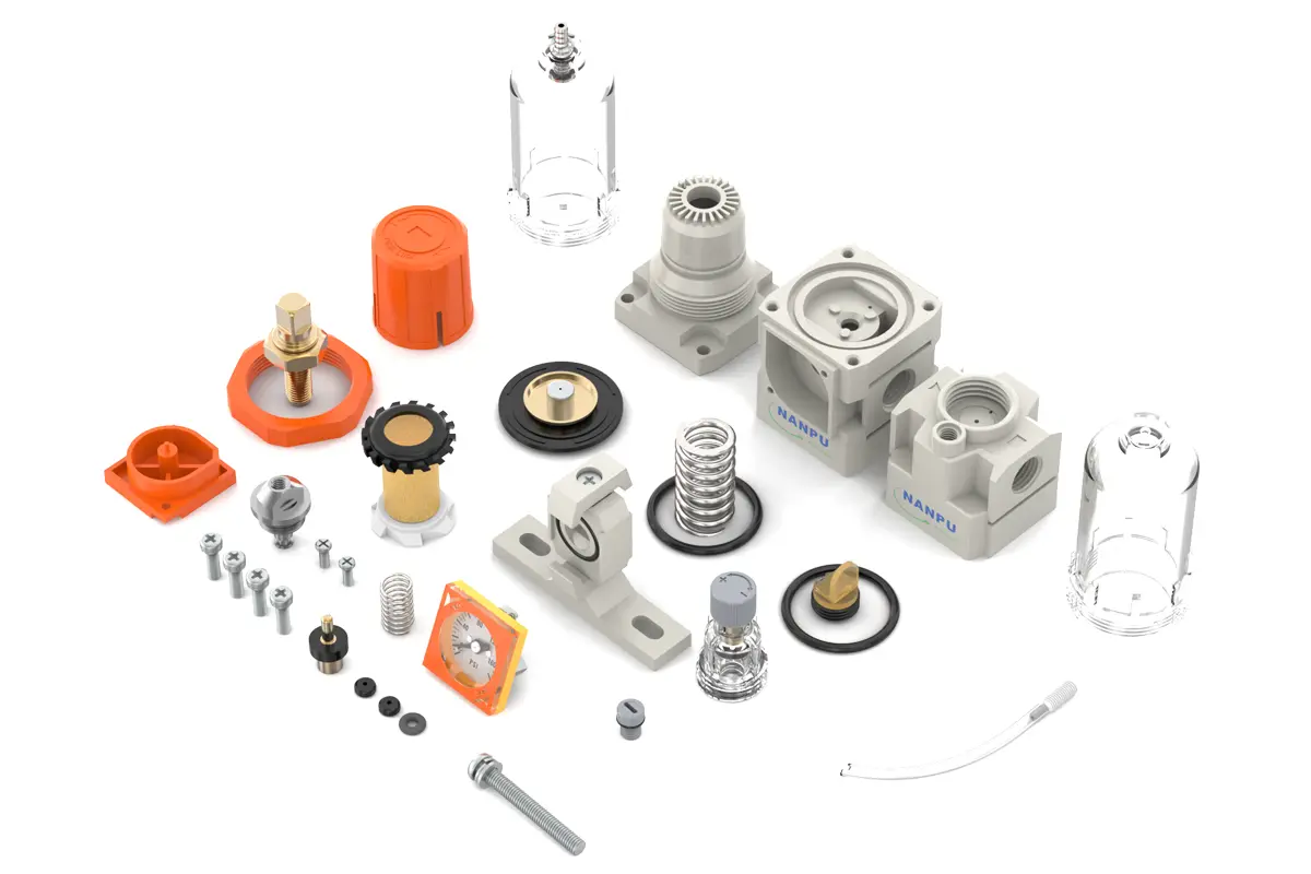
| Product Benefits | |
| All Portsize Piggyback Air Filter (5 Micron Element Standard), Regulator & Lubricator (FRL) | |
| Dry Air, Pressure Regulating & Lubricate Air | |
| Temperature Range: 41-140℉ (5-60℃) |
NANPUInstallation and Operating
1.Preparation
Each calibration component shall comply with the maximum flow rate specification.
Prior to installation, all ports and connectors shall be thoroughly cleaned to prevent dust ingress into the air circuit.
Ensure that the air flow direction is strictly aligned with the arrow markings on the product housing, and verify that port and thread dimensions are properly matched.
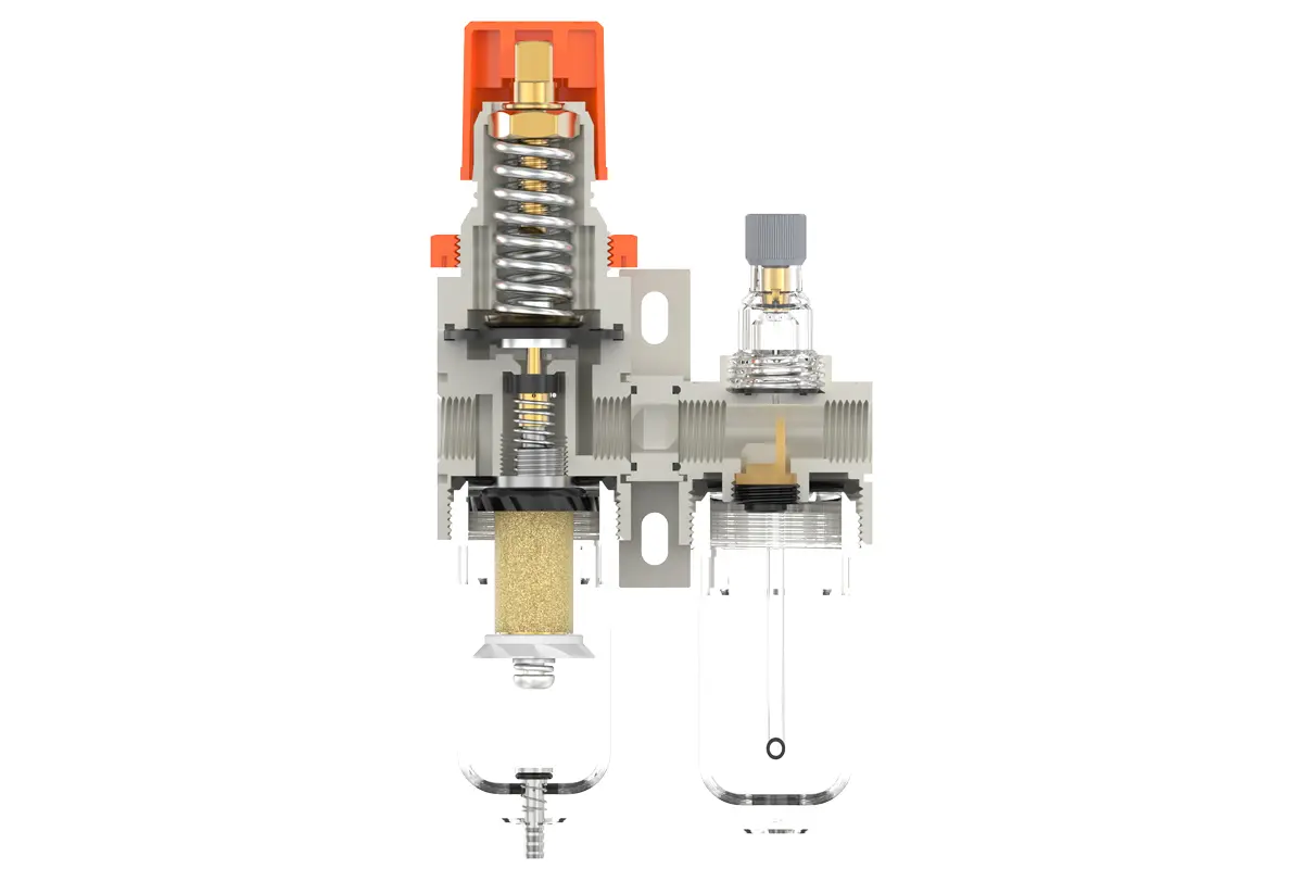
2. Pressure Adjustment
Elevate the pressure gauge knob and initiate rotation:Clockwise rotation shall gradually increase the pressure in a uniform manner, while counterclockwise rotation will decrease it.Cease rotation upon reaching the target pressure value and securely depress the knob. Non - compliance with this step may result in pressure leakage issues.
3. Dial Reading
Ensure the pressure gauge is securely mounted to the main assembly. During pressure adjustment, monitor the gauge closely to verify that readings increase and decrease in a uniform manner.
4.Drainage
The drain valve operates automatically. In the absence of pressure, it will unlatch to discharge moisture and seal when air flows through. Once the water level reaches or exceeds the allowable maximum, immediate draining is mandatory; failure to do so will result in decreased dehumidification efficiency. The fitting on the drain assembly is designed for connecting an air hose and can be easily detached per specific operational requirements.
5.Oil Adjustment
Rotate the needle valve clockwise to increase the oil intake rate. Conversely, counterclockwise rotation of the needle valve will decrease the oil intake rate or bring it to a complete halt.
6.Refueling
Turn the filling screw clockwise. The oil volume introduced shall not exceed 80% of the container's capacity. Upon completion of the refilling procedure, securely tighten the filling screw.