


NR200 1/4" AR Air Regulator
description1
NR200 1/4" AR Air Regulator
NR200 1/4" AR Air Regulator
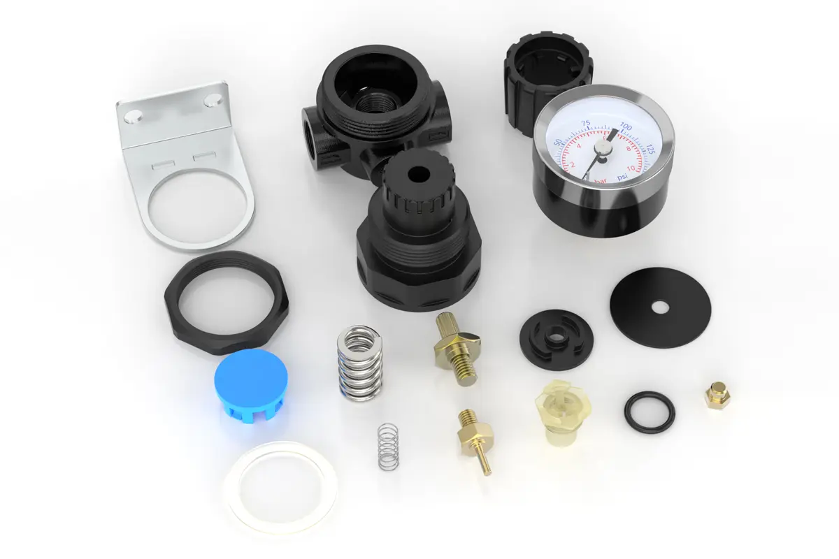
NANPU NR200 1/4" AR Air Regulator
| NR | 200 | 02 | BSP |
| Series Number | Body Size | Port Size | Thread Type |
| NR | 200 | 01:1/8“ | |
| 02:1/4” |
NANPUTechnical Specifications
| Technical Specifications | |
| Max Input Pressure | 1.2Mpa{12.24kgf/cm²} /174.04Psi |
| Max Operating Pressure | 1.0Mpa{10.2kgf/cm²} /145Psi |
| Temperature Range | 5~60℃ |
| Pressure Range | (0.51~8.7kgf/cm² )/0~125Psi |
| Model | Specification |
| R200 | 500 |
| Product Benefits |
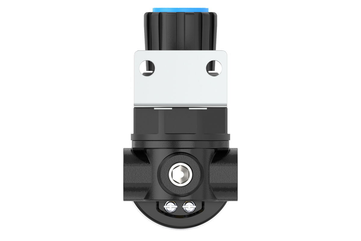
| The assembly of all calibration shall meet the maximum flow requirement. Please clean the port and fitting before installation, it will effectively avoid bring dust to the air path. Pay attention to direction of air flow and arrow pointing on product body if correct, minding port and thread size if match. |
NANPUPreparation
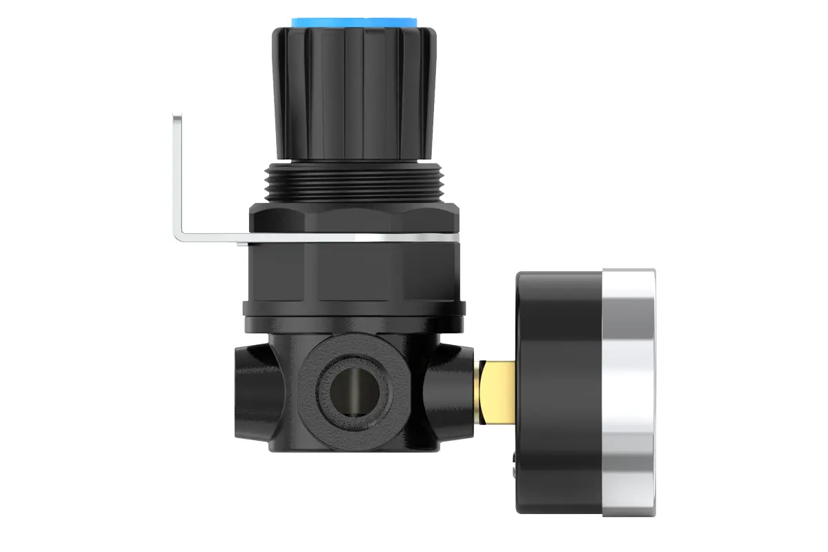
All calibration modules must fully adhere to the maximum flow rate criteria outlined in the technical specifications. Such adherence is crucial to safeguarding the system’s optimal functionality and dependability.Before fitting, it is mandatory to thoroughly sanitize all ports and connectors using suitable cleaning solutions and procedures. This comprehensive sanitization effectively keeps dust, particles and other impurities from entering the air circuit, thereby preserving the compressed air system’s integrity and operational efficiency.During fitting, close attention should be devoted to confirming that the air flow direction matches exactly the arrow indicators on the product casing. Additionally, it is necessary to verify that the port and thread dimensions are perfectly compatible with the respective components. This careful confirmation of measurements and flow direction is essential to preventing possible installation mistakes that could lead to system breakdowns or performance losses.
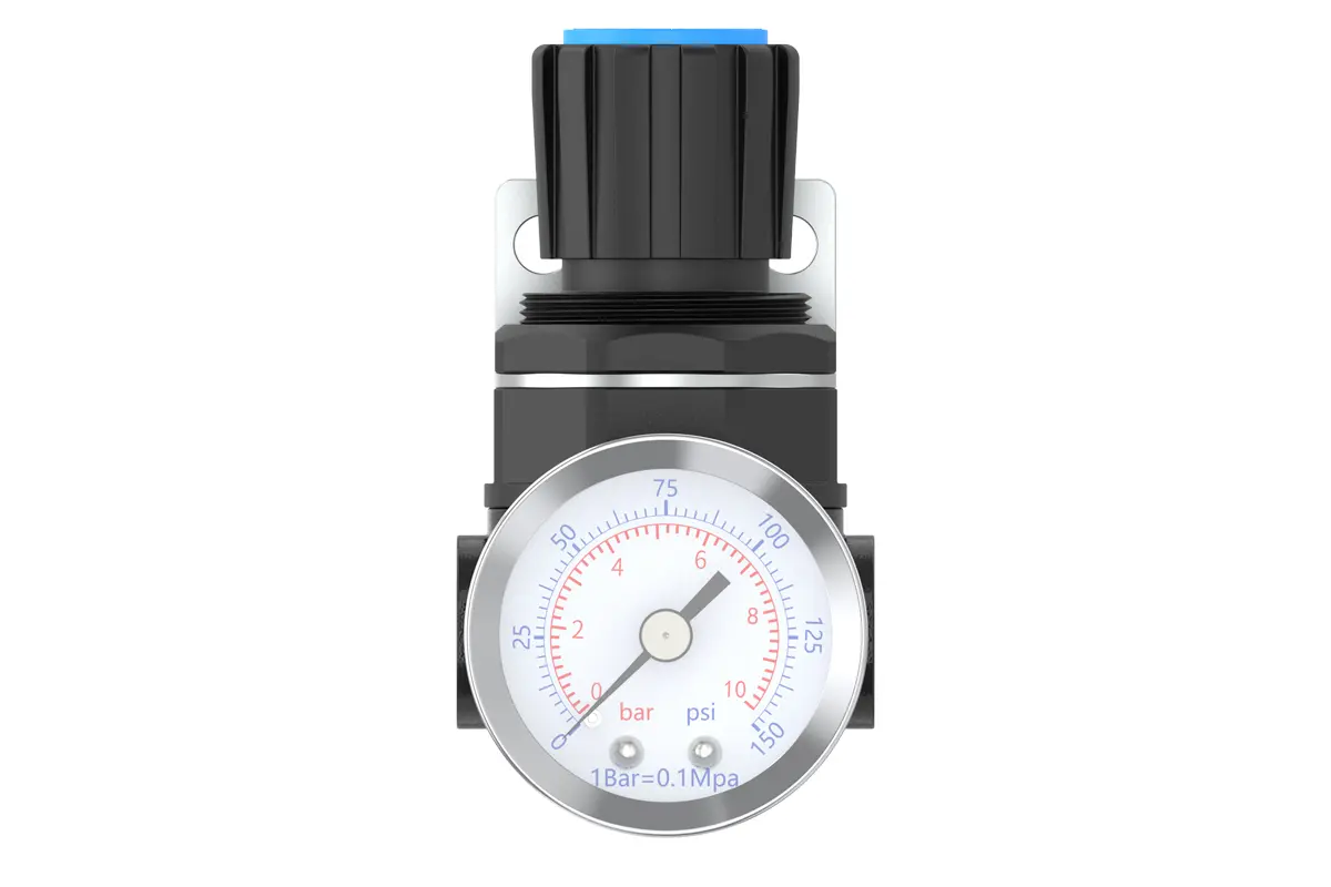
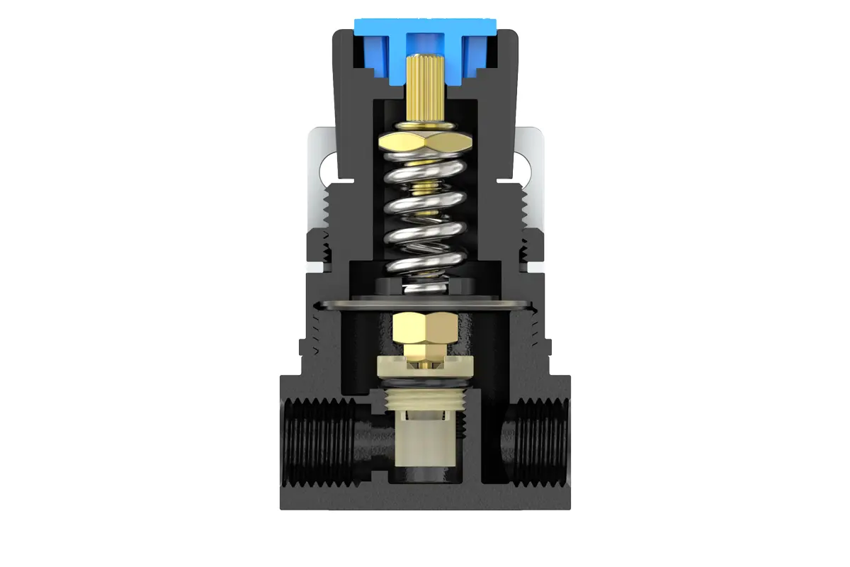
To regulate pressure, first, raise the pressure gauge knob to the unlocked state. Next, turn the knob to adjust the pressure parameters. A clockwise turn will produce a gradual and uniform pressure rise, while a counterclockwise turn will initiate a steady pressure drop.
It is essential to closely observe the pressure gauge and stop turning once the target pressure value is achieved. After reaching the required pressure level, firmly fasten the knob to fix the setting. Inadequate securing of the knob may cause seal damage, possibly leading to leakage problems that could compromise the system's functionality and safety. During operation, perform regular inspections on the locked knob to ensure pressure remains stable and within the designated range.
Guarantee the pressure gauge is firmly and correctly attached to the main unit via suitable mounting tools and techniques, complying with the specified torque standards to avert potential leakage or displacement. Throughout the pressure regulation process, closely observe the pressure gauge to verify that readings rise and fall in a steady, uniform fashion without erratic fluctuations or seizing. Abnormal gauge behavior may indicate problems like internal clogs, damaged parts, or incorrect calibration, which require immediate inspection and correction to sustain the pressure monitoring system’s accuracy and dependability.