


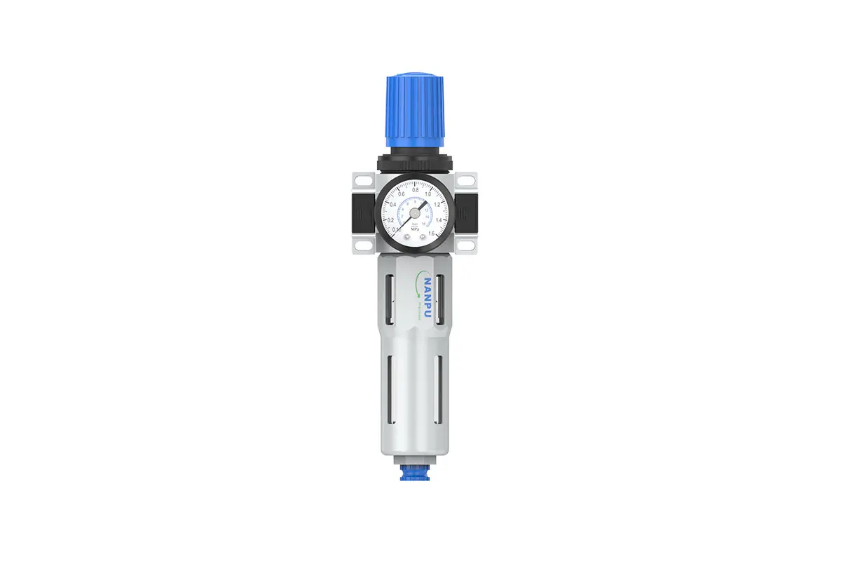
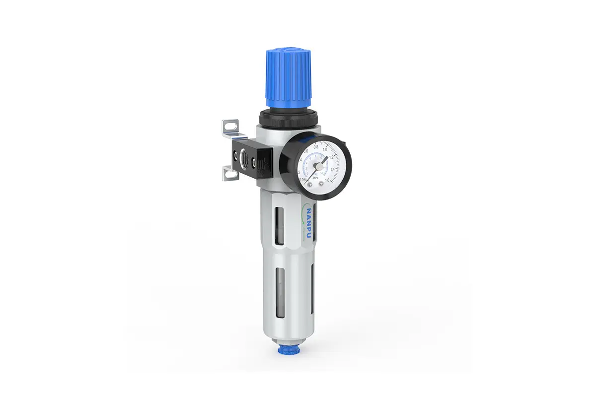
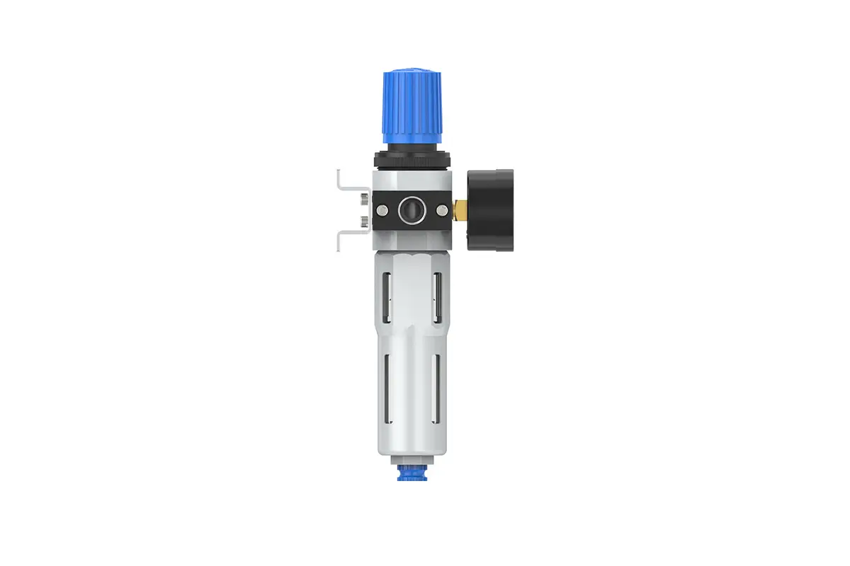
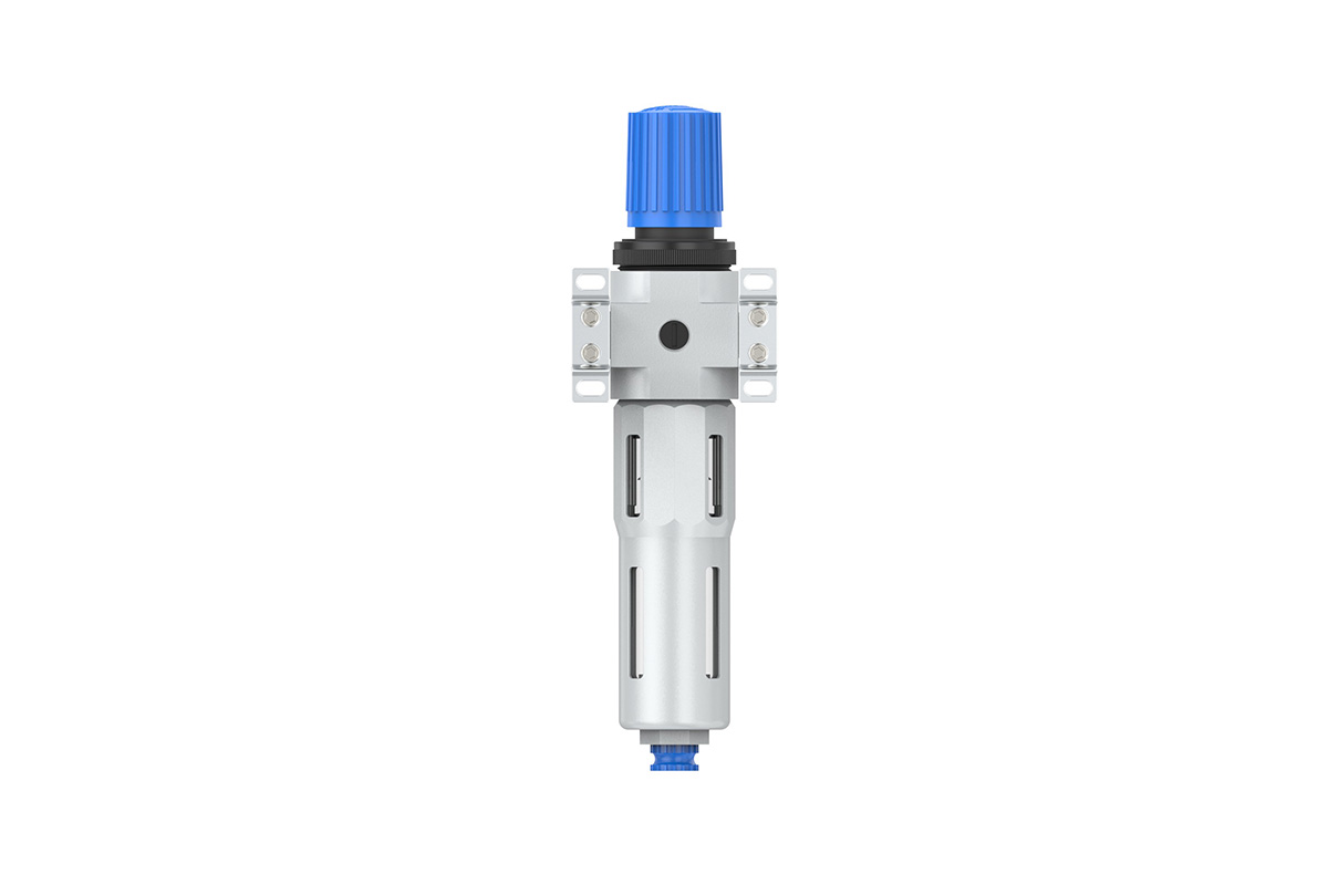
LFR-1/4 3/8-MINI,LFR-3/8 1/2-MIDI F.R.L.Combination Air Filter, Regulator & Lubricator
description1
LFR-1/4 3/8-MINI,LFR-3/8 1/2-MIDI F.R.L.Combination Air Filter, Regulator & Lubricator
Manual Drain LFR-1/4 3/8-MINI,LFR-3/8 1/2-MIDI F.R.L.Combination Air Filter, Regulator & Lubricator
Auto Drain LFR-1/4 3/8-MINI,LFR-3/8 1/2-MIDI-D F.R.L.Combination Air Filter, Regulator & Lubricator
NANPULFR-1/4 3/8-MINI,LFR-3/8 1/2-MIDI
| LFR | 1/4" | MINI | BSP | D |
| Series Number | Port Size | Body Size | Thread Type | Drainage Method |
| 1/4" | MINI | BSP | Blank: Differential Pressure Drain | |
| 3/8" | MIDI | NPT | A: Manual Drain | |
| 1/2" | PT | D: Auto Drain |
NANPUTechnical Specifications
| Model | Model | |
| Manual Drain | Auto Drain | (L/min)Rated Flow Rate |
| LFR-1/4-MINI | LFR-1/4-MINI-D | 1000 |
| LFR-3/8-MINI | LFR-3/8-MINI-D | 1200 |
| LFR-3/8-MIDI | LFR-3/8-MIDI-D | 2000 |
| LFR-1/2-MIDI | LFR-1/2-MIDI-D | 2600 |
| Max Input Pressure | 1.6Mpa{16.32kgf/cm²} 232Psi |
| Max Operating Pressure | 1.2Mpa{12.24kgf/cm²} 174Psi |
| Temperature Range | 5~60℃ |
| Filtration Accuracy | 5μm、40μm |
| Body Material | Aluminium/Zinc |
| Bowl Guard | YES |
| Pressure Range | LFR-1/4~1/2:0.05~1.2Mpa(0.51~12.24kgf/cm²) |
1. Preparation
All calibration assemblies must satisfy the maximum flow specification.
Prior to installation, thoroughly cleanse all ports and fittings to effectively prevent dust from entering the air passage.
Verify that the air flow direction aligns with the arrow markings on the product body and ensure the port and thread dimensions are properly matched.
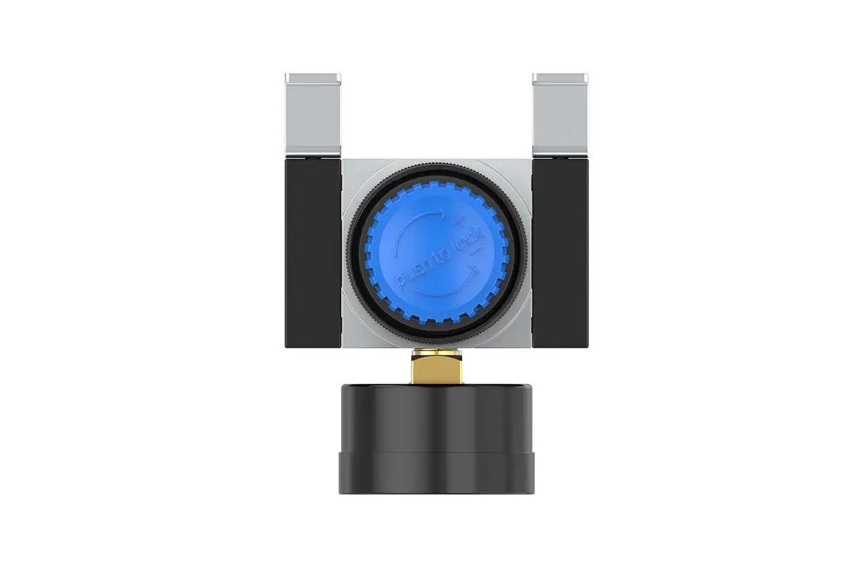
2. Pressure Adjustment
Raise the pressure gauge knob and begin rotating it. A clockwise rotation will cause a steady and consistent increase in pressure, whereas a counterclockwise rotation will induce a pressure decrease.
Once the desired pressure value is attained, cease rotation and firmly depress the knob to secure it. Failing to perform this locking step may give rise to pressure leakage issues.
3. Dial Reading
Ensure the pressure gauge is securely affixed to the main assembly. During pressure adjustment, meticulously monitor the gauge to verify that the readings exhibit smooth and uninterrupted fluctuations.
4. Drainage
The drainage column operates automatically, opening to discharge when pressure is absent and closing when air flows. If the water level exceeds the upper threshold, immediate drainage is critical; failing to do so will cause diminished dehumidification performance. The fitting on the drain head is designed for air hose attachment and can be detached per specific operational requirements.
5. Oil Adjustment
Rotate the needle valve clockwise (in the “+” direction) to increase the oil suction rate. Conversely, rotating the needle valve counterclockwise (in the “-” direction) will decelerate or stop the oil suction process.
6. Refueling
Rotate the fueling screw clockwise, ensuring the volume of oil added does not exceed 80% of the bowl's capacity. Once completing the refueling process, securely tighten the fueling screw.