


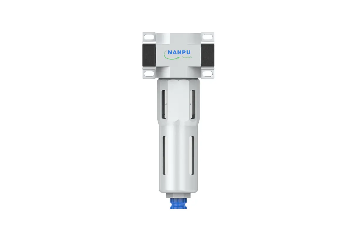
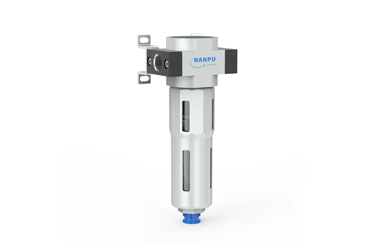
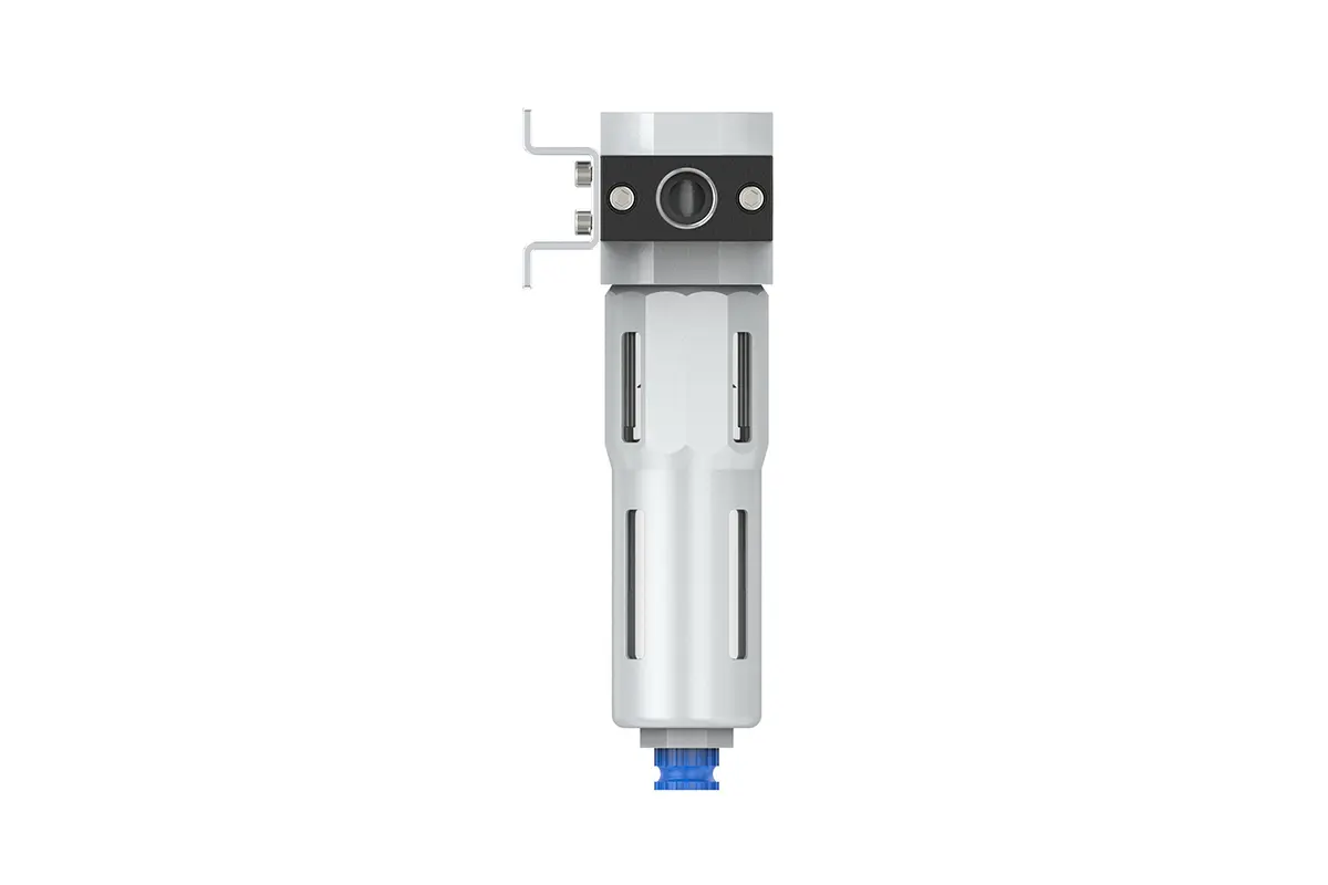
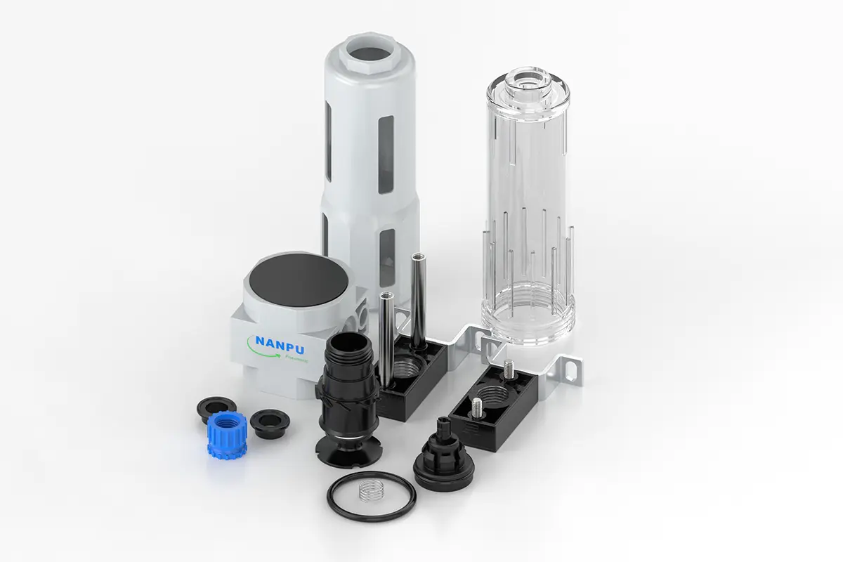
LF-1/4 3/8-MINI,LF-3/8 1/2-MIDI Air Filter
description1
LF-1/4 3/8-MINI,LF-3/8 1/2-MIDI Air Filter
LF-1/4 3/8-MINI,LF-3/8 1/2-MIDI Air Filter
NANPULF-1/4 3/8-MINI,LF-3/8 1/2-MIDI Air Filter
| LFR | 1/4" | MINI | BSP | D |
| Series Number | Port Size | Body Size | Thread Type | Drainage Method |
| 1/4" | MINI | BSP | Blank: Differential Pressure Drain | |
| 3/8" | MIDI | NPT | A: Manual Drain | |
| 1/2" | PT | D: Auto Drain |
NANPUTechnical Specifications
| Model | Model | |
| Manual Drain | Auto Drain | (L/min)Rated Flow Rate |
| LF-1/4-MINI | LF-1/4-MINI-D | 1000 |
| LF-3/8-MINI | LF-3/8-MINI-D | 1200 |
| LF-3/8-MIDI | LF-3/8-MIDI-D | 2000 |
| LF-1/2-MIDI | LF-1/2-MIDI-D | 2600 |
| Max Input Pressure | 1.6Mpa{16.32kgf/cm²} 232Psi |
| Max Operating Pressure | 1.2Mpa{12.24kgf/cm²} 174Psi |
| Temperature Range | 5~60℃ |
| Filtration Accuracy | 5μm、40μm |
| Body Material | Aluminium/Zinc |
| Bowl Guard | YES |
| Pressure Range | FRC-1/4~1/2:0.05~1.2Mpa(0.51~12.24kgf/cm²) |
All calibration assemblies must be meticulously engineered and assembled to fully conform to maximum flow rate specifications. Such compliance is critical for ensuring optimal system performance and reliability. Prior to installation, all ports and fittings shall be thoroughly cleaned using appropriate solvents and tools to effectively prevent dust and debris from infiltrating the air pathway, thereby mitigating risks of potential blockages. During installation, carefully verify that the air flow direction aligns with the arrow markings on the product body and ensure precise matching of port dimensions and thread sizes to guarantee a secure, leak-free connection.
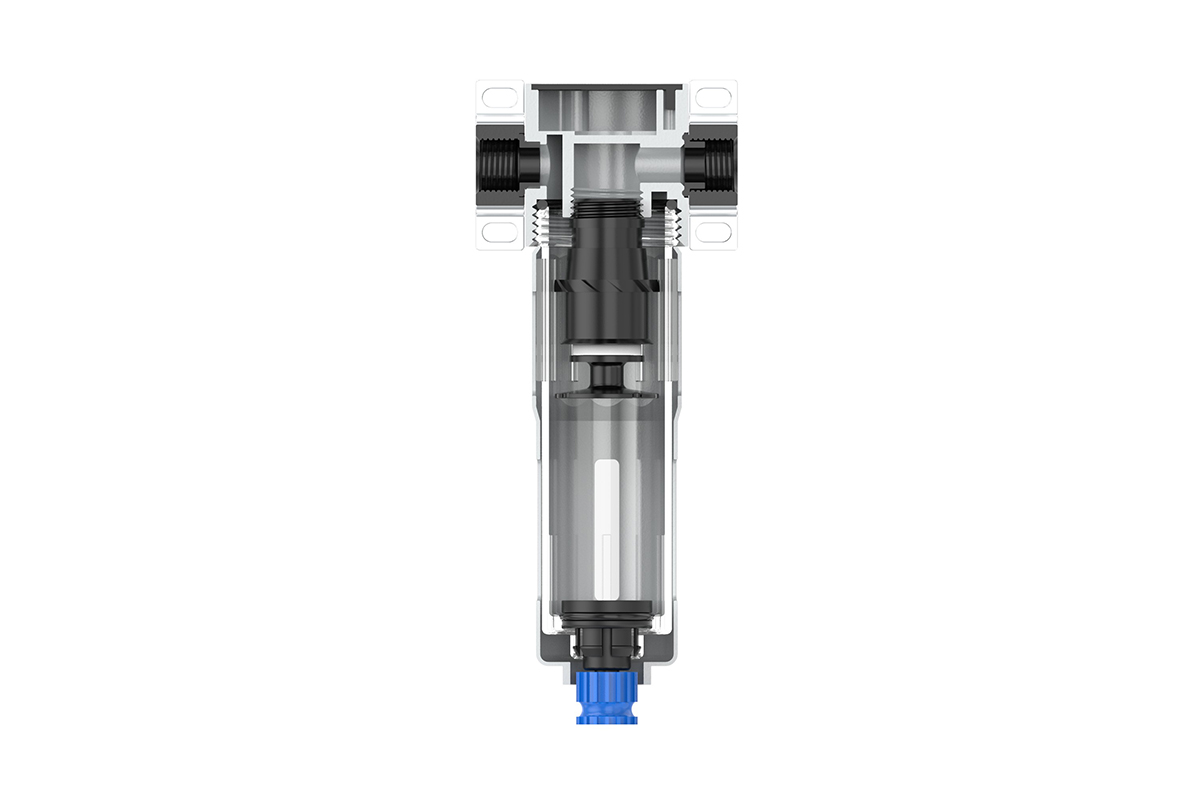
The filtration process is administered via an automated system, utilizing advanced mechanical and filtration technologies to ensure consistent and efficient purification. The 5-micron filter element, a critical component of this system, employs a precision-engineered multi-layer structure. It effectively intercepts and removes various contaminants, including sediment, suspended solids, colloids, rust, and other particulate matter within the air stream. This meticulous filtration not only protects downstream equipment but also ensures the delivery of high-quality, clean air that meets rigorous industrial standards.
The drain column incorporates an automated actuation mechanism. In the absence of air pressure, it activates to discharge accumulated condensate, thereby preventing water accumulation. When compressed air is flowing, the column seals securely to maintain system integrity and prevent backflow. However, close monitoring of the water level within the column is critical. If the water level exceeds the specified maximum threshold, immediate manual drainage is required. Neglecting this action can result in diminished dehumidification efficiency, potential damage to downstream components, and reduced overall system performance.