


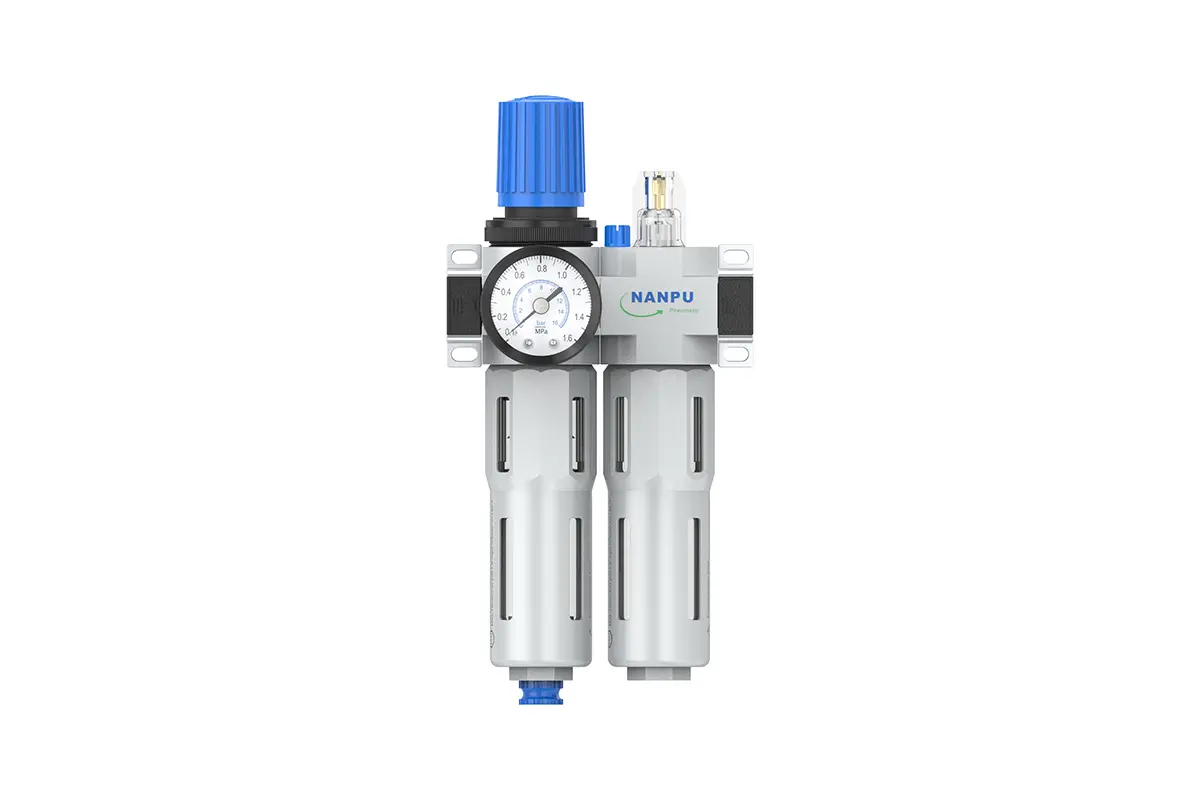
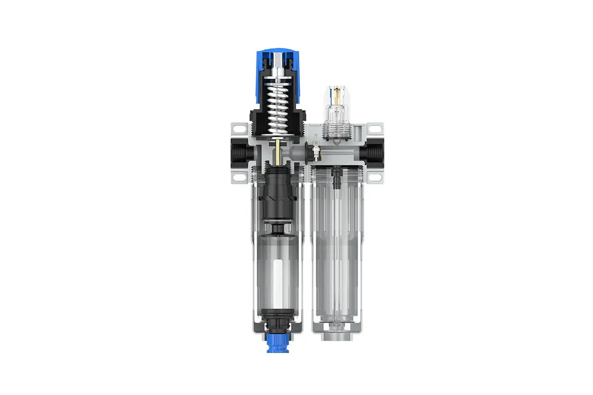
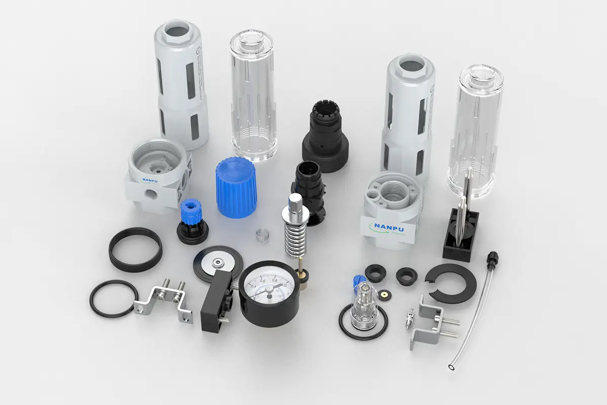
FRC-1/4 3/8-MINI,FRC-3/8 1/2-MIDI F.R.L.Combination Air Filter, Regulator & Lubricator
description1
FRC-1/4 3/8-MINI,FRC-3/8 1/2-MIDI F.R.L.Combination Air Filter, Regulator & Lubricator
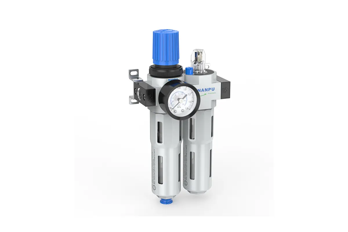
Manual Drain FRC-1/4 3/8-MINI,FRC-3/8 1/2-MIDI F.R.L.Combination Air Filter, Regulator & Lubricator
Auto Drain FRC-1/4 3/8-MINI,FRC-3/8 1/2-MIDI-D F.R.L.Combination Air Filter, Regulator & Lubricator
NANPUFRC-1/4 3/8-MINI,FRC-3/8 1/2-MIDI
| FRC | 1/4" | MINI | BSP | D |
| Series Number | Port Size | Body Size | Thread Type | Drainage Method |
| 1/4" | MINI | BSP | Blank: Differential Pressure Drain | |
| 3/8" | MIDI | NPT | A: Manual Drain | |
| 1/2" | PT | D: Auto Drain |
NANPUTechnical Specifications
| Model | Model | |
| Manual Drain | Auto Drain | (L/min)Rated Flow Rate |
| FRC-1/4-MINI | FRC-1/4-MINI-D | 1000 |
| FRC-3/8-MINI | FRC-3/8-MINI-D | 1200 |
| FRC-3/8-MIDI | FRC-3/8-MIDI-D | 2000 |
| FRC-1/2-MIDI | FRC-1/2-MIDI-D | 2600 |
| Max Input Pressure | 1.6Mpa{16.32kgf/cm²} 232Psi |
| Max Operating Pressure | 1.2Mpa{12.24kgf/cm²} 174Psi |
| Temperature Range | 5~60℃ |
| Filtration Accuracy | 5μm、40μm |
| Body Material | Aluminium/Zinc |
| Bowl Guard | YES |
| Suggested Oil | Turbine Oil No. 1 ISO-VG32 |
| Pressure Range | FRC-1/4~1/2:0.05~1.2Mpa(0.51~12.24kgf/cm²) |
1. Preparation
All calibration units must meet the peak flow requirement.
Before installation, clean all ports and connectors completely to efficiently stop dust from getting into the air channel.
Check that the air flow direction corresponds to the arrow signs on the product casing and make sure the port and thread sizes are correctly matched.
2. Pressure Adjustment
Lift the pressure gauge knob and start turning it. Turning it to the right will lead to a steady and continuous rise in pressure, while turning it to the left will make the pressure drop.
When the target pressure value is reached, stop turning and press the knob firmly to lock it. Not taking this locking action might result in pressure leakage problems.
3. Dial Reading
Make sure the pressure gauge is firmly attached to the main component. While adjusting the pressure, carefully observe the gauge to confirm that the readings show smooth and continuous changes.
4. Drainage
The drainage column functions automatically, opening to release when pressure is absent and shutting when air flows. If the water level surpasses the maximum limit, prompt drainage is essential; neglecting this will lead to reduced dehumidifying efficiency. The connector on the drain head is made for attaching an air hose and can be removed according to particular operating needs.
5. Oil Adjustment
Turn the needle valve to the right (toward the “+” symbol) to boost the oil intake speed. On the contrary, turning the needle valve to the left (toward the “-” symbol) will slow down or stop the oil suction procedure.
6. Refueling
Turn the oil - filling screw to the right, making sure that the amount of oil poured in does not go beyond 80% of the bowl's capacity. After finishing the oil - adding process, tightly fasten the oil - filling screw.