


FR Filter Regulator
description1
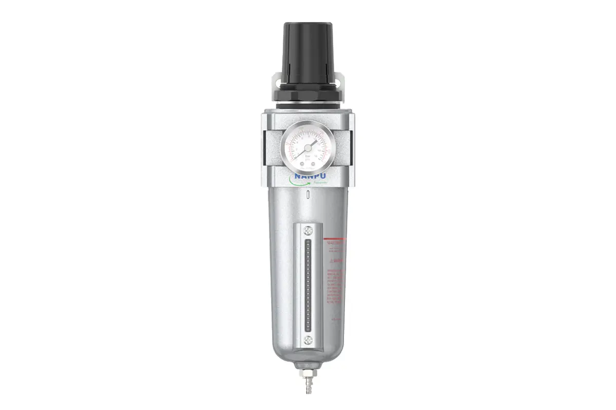
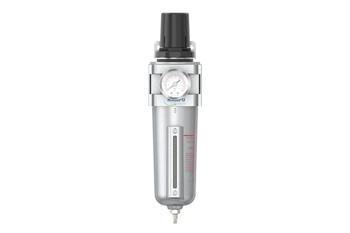
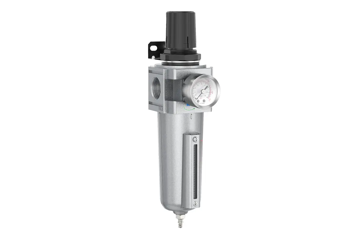
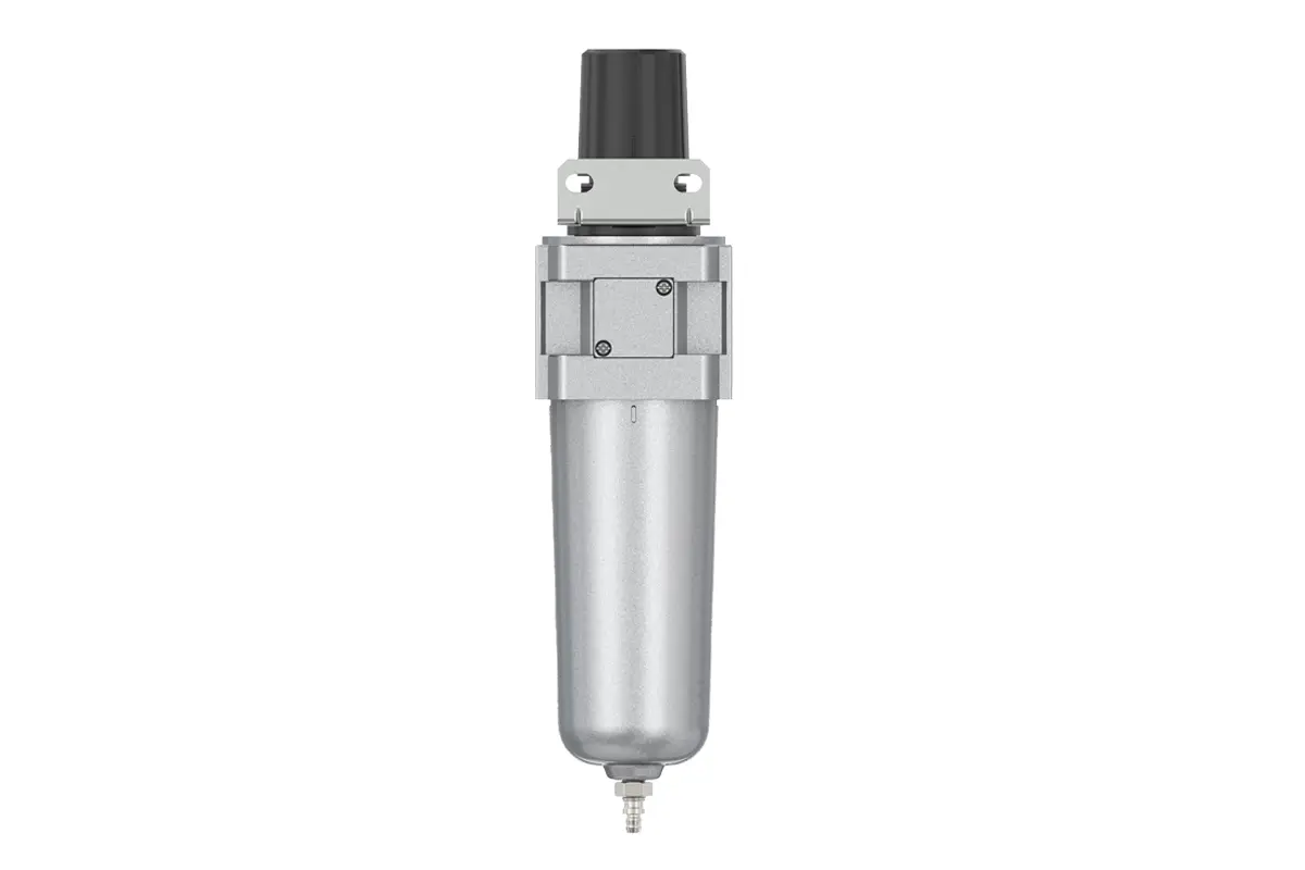
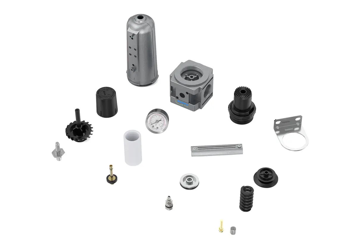
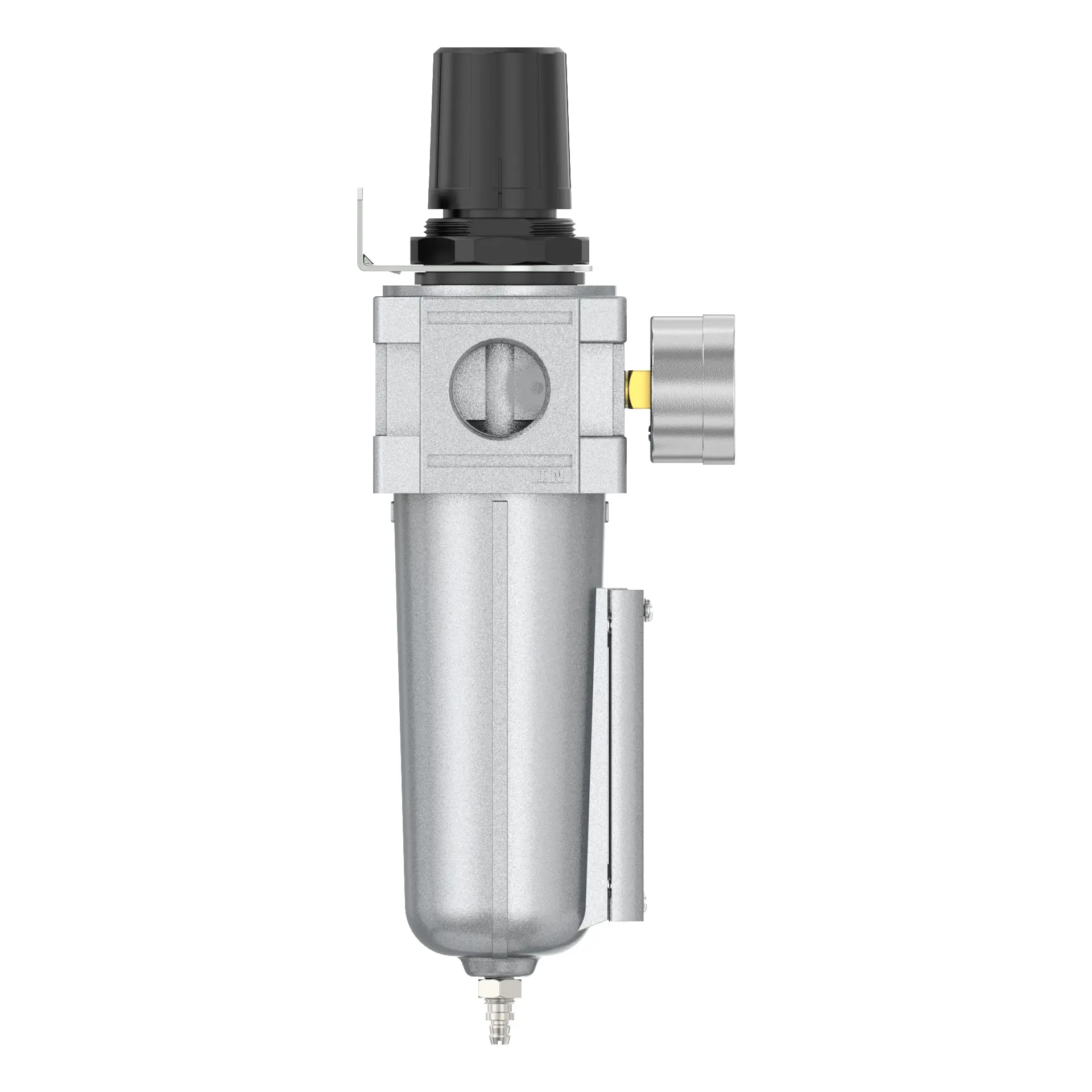
FR44/FR46 Air Filter, Regulator
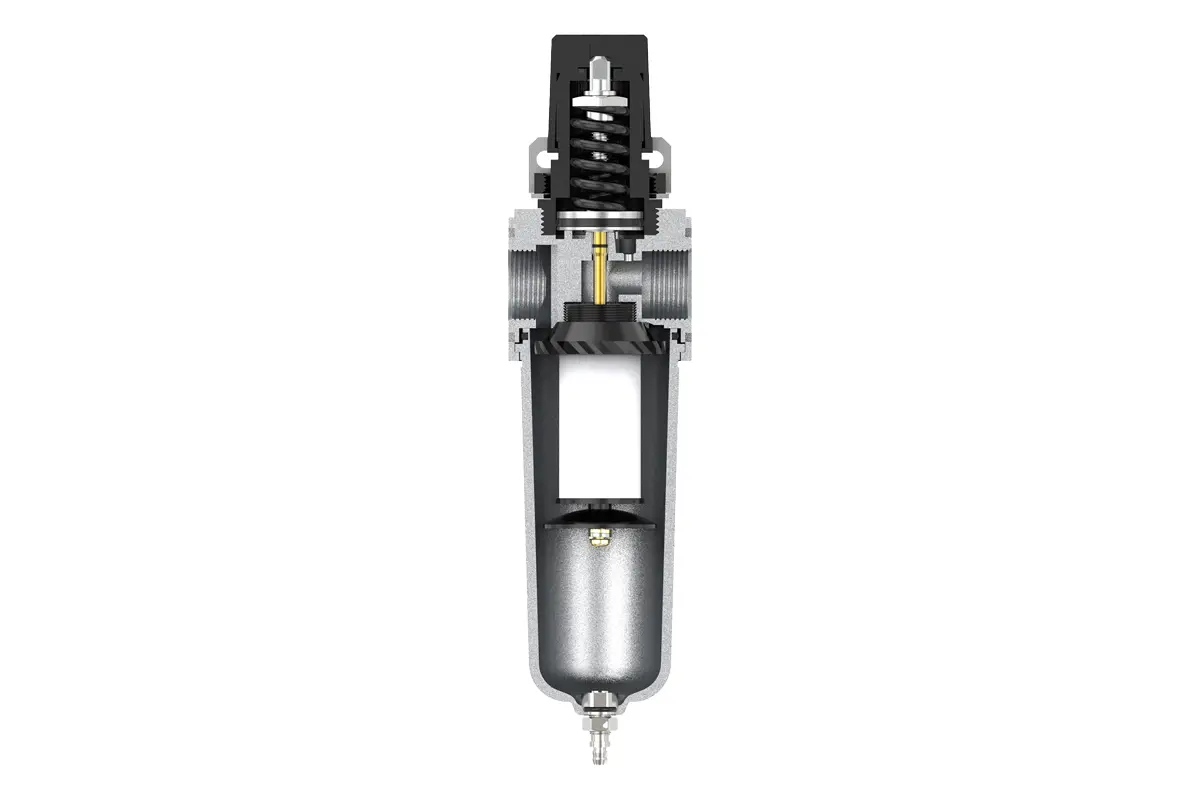
Manual Drain FR44/FR46 Air Filter, Regulator
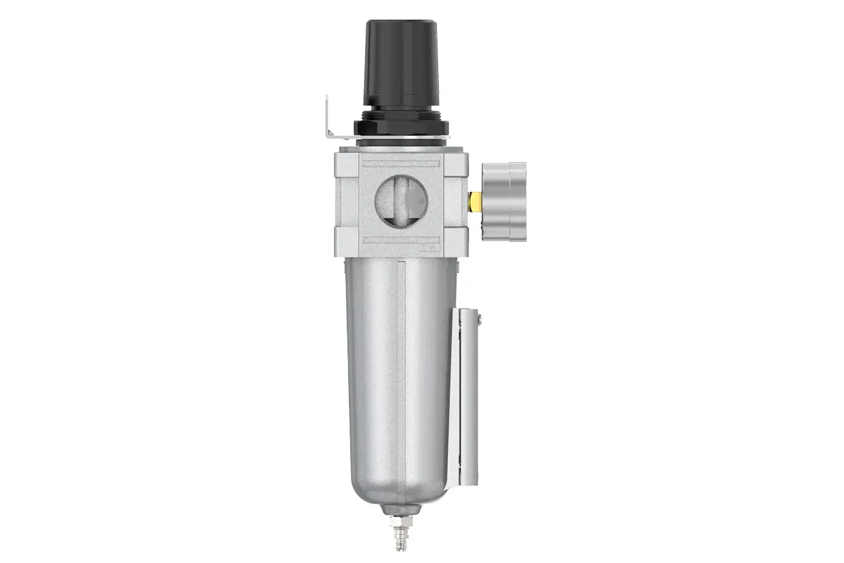
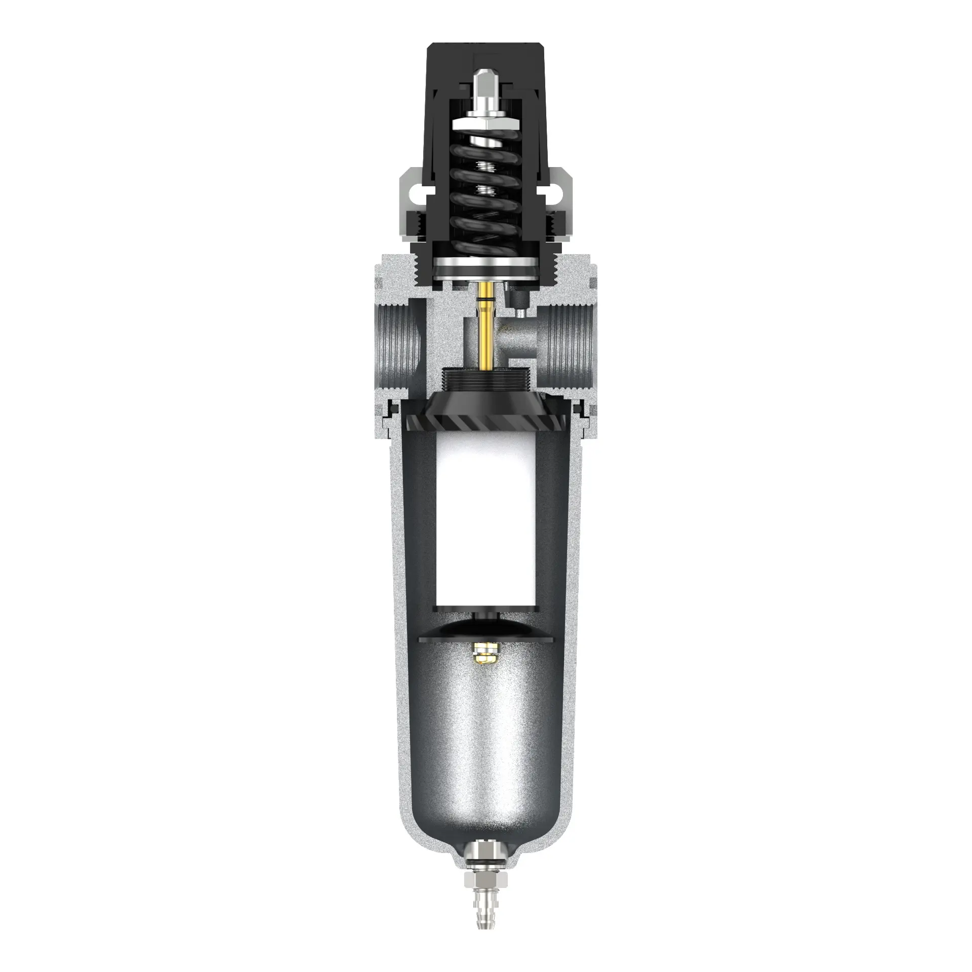
Auto Drain FR44-D/FR46-D Air Filter, Regulator
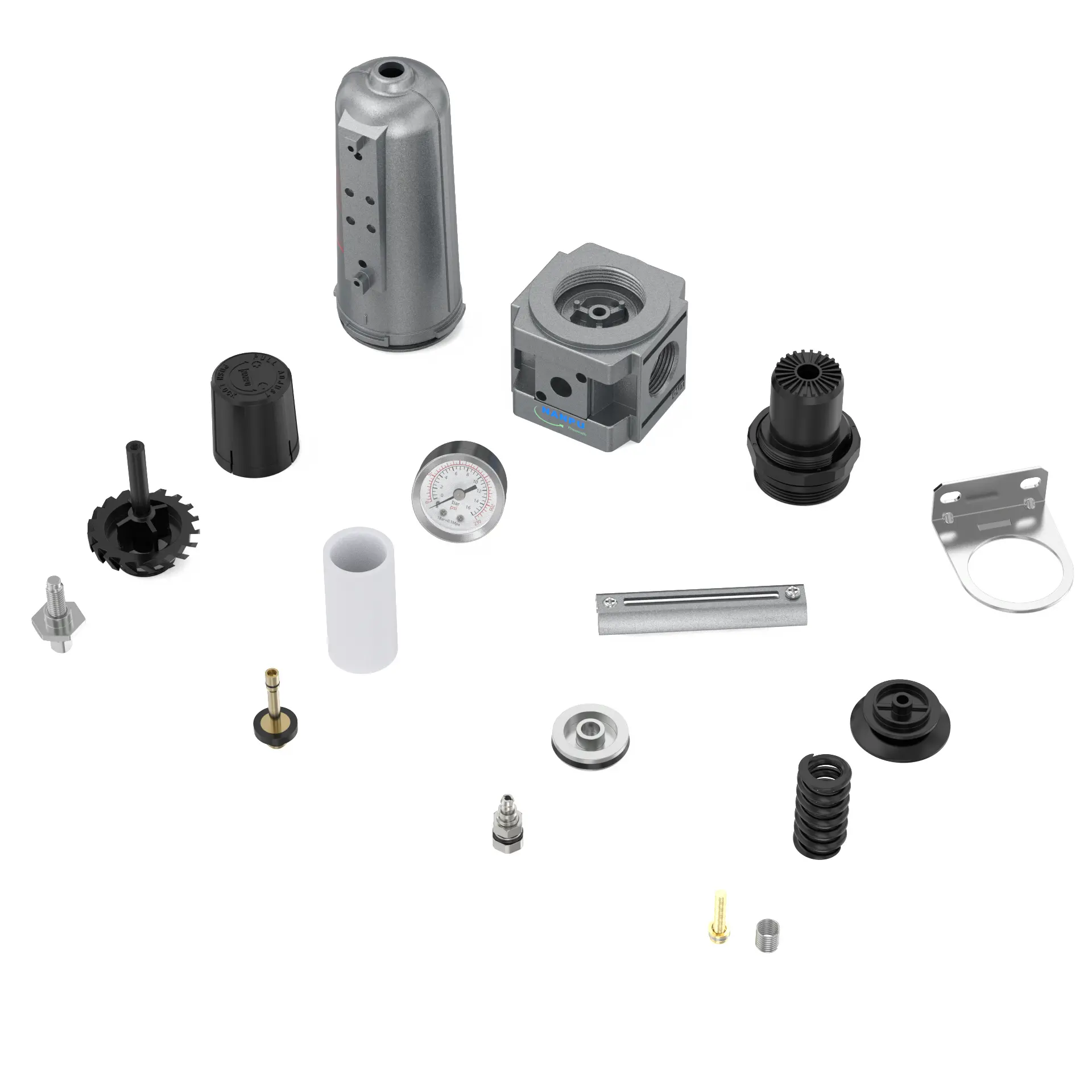
NANPUFR Filter Regulator
| FR | 44 |
| Series Number | Port Size |
| 04:1/2 | |
| 06: 3/4 |
NANPUTechnical Specifications
| Technical Specifications | |
| Max Input Pressure | 1.6Mpa{16.32kgf/cm²} 232.06Psi |
| Max Operating Pressure | 1.48Mpa{15.09kgf/cm²} 214.7Psi |
| Temperature Range | -5~60℃ |
| Filtration Accuracy | 0.01μm、 5μm、40μm |
| Bowl Material | Aluminum Alloy |
| Bowl Guard | FRPD-44~46 |
| Pressure Range | FRPD-44~46:0.05~14.8Mpa(0.51~15.0kgf) |
| Model | Model |
| Manual Drain | Auto Drain |
| FRPD44 | FRPD44D |
| FRPD46 | FRPD46D |
| Product Benefits |
| High Pressure Resistance】Works Perfectly in the Pressure Environment of 7-215 psi; 【High Degree of Safety】Excellent Metal Bowl w/ Visible Sight Glass in Every Stage Protect You and the System throughout the Entire Process. |
| 【Stage 1: Filter & Regulator】Compressed Air Water Trap Filter Equipped with 5 Micron Element, which has Excellent Filtering Performance, Much Longer Life and Reuse Feasibility, Remove Most of Moisture and Particles in the Air Line; Pressure Regulator Accurately Adjust and Stabilize the Air Pressure. |
| 【Stage 2: Coalescing Filter】The Coalescing Filter is Equipped with a 0.01 Micron Element that can Remove 99.9% of Moisture, Smaller Particles and Oil, which Pass Through Stage 1 Combo. When the Filter Element needs to be Replaced, the Red Indicator will Pop Up. |
| 【Stage 3: Desiccant Air Dryer】The Desiccant Air Dryer allows the Air to be Thoroughly Dried and Cleaned before it Enters your Pneumatic Tools. The Desiccant Beads need to be Added to the Metal Bowl. When it needs to be Replaced, the Beads will Change from Blue to Pink. |
NANPUInstallation and Operating
1.Preparation
All calibration assemblies shall conform to the maximum flow rate specification.
Before installation, meticulously cleanse the ports and fittings to effectively preclude dust ingress into the air pathway.
Confirm that the air flow direction corresponds with the arrow markings on the product body, and ensure proper matching of port and thread dimensions.
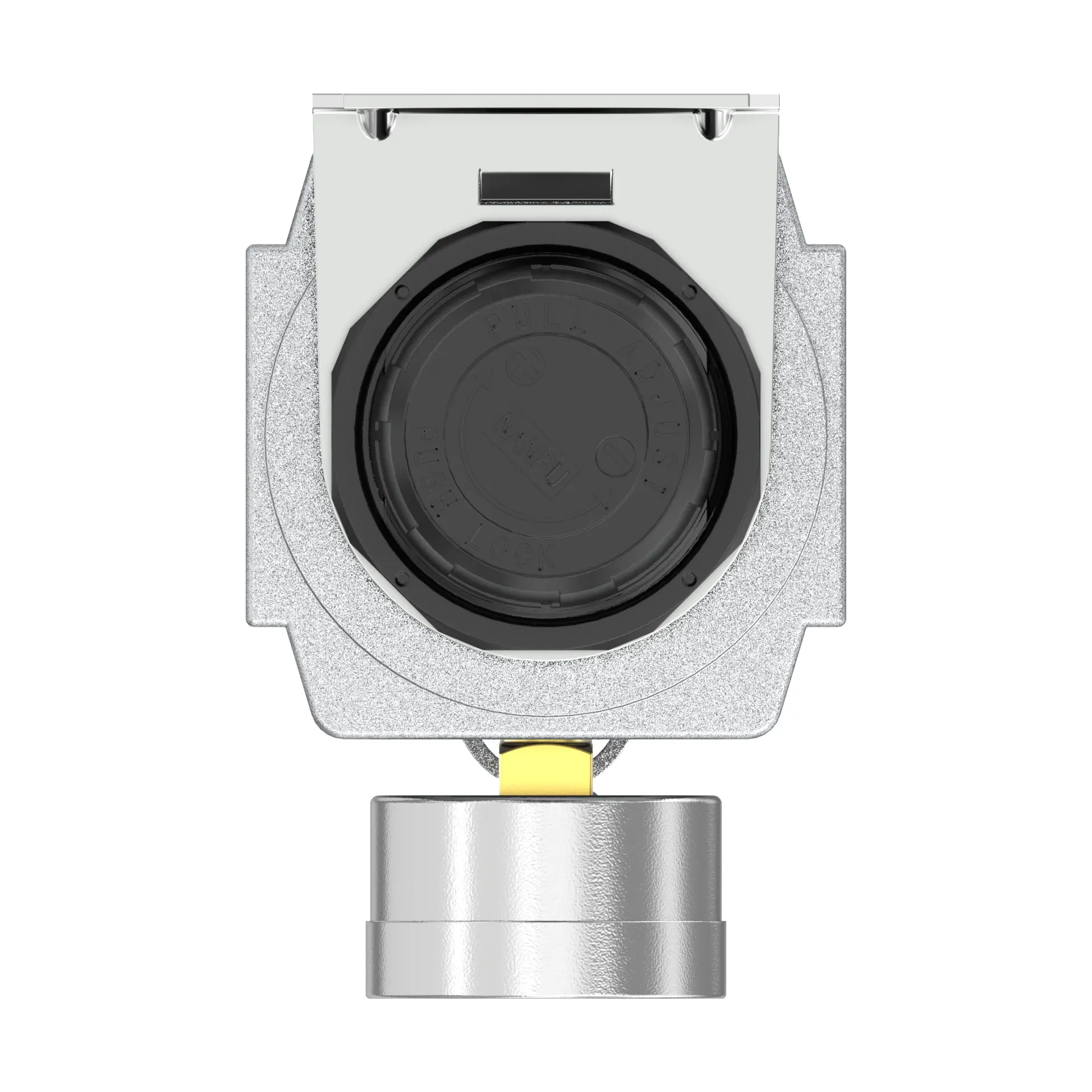
2. Pressure Adjustment
Raise the pressure gauge knob and execute rotation. A clockwise turn will induce a gradual, steady pressure elevation, whereas a counterclockwise turn will effect pressure reduction. Upon reaching the target pressure value, halt rotation and firmly secure the knob. Inadequate locking of the knob may precipitate potential leakage, thereby compromising system integrity.
Utilize an appropriate wrench to torque the fittings to the recommended specification to prevent leakage. During initial installation, air release may occur. This is not a leak but rather a consequence of internal and external pressure disparity, necessitating the expulsion of excess air. In such cases, allow the system adequate time to reach equilibrium, after which it will operate optimally.