


DFR-10 1" DFR Air Drying System
description1
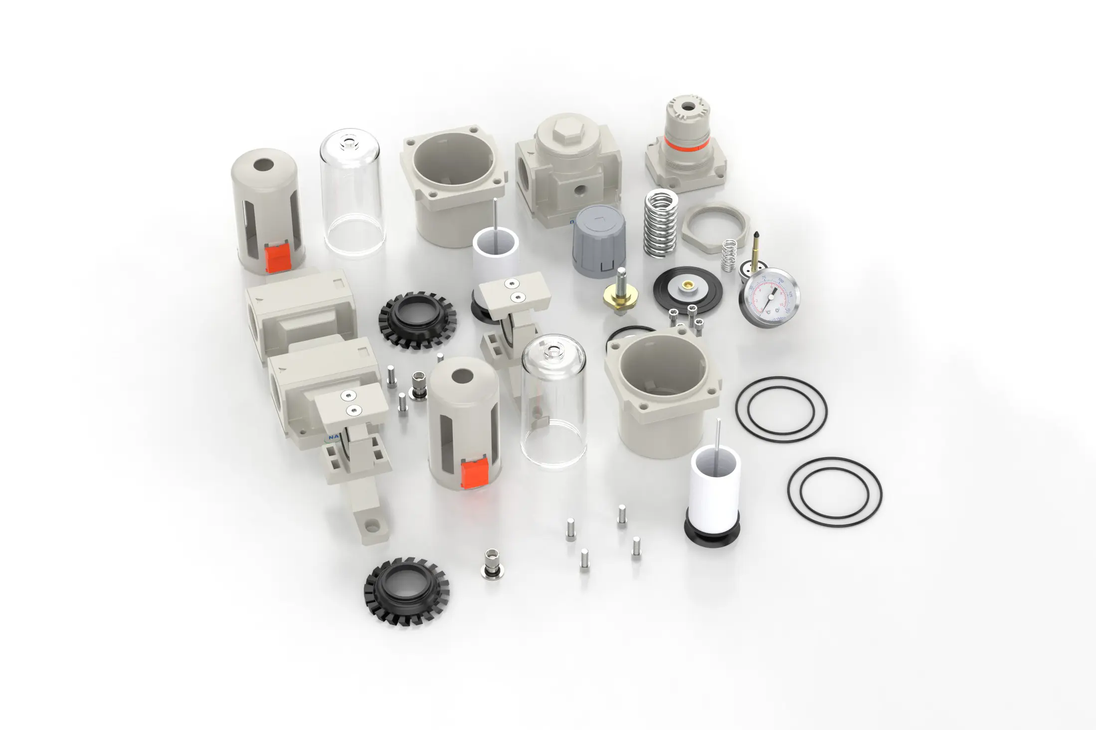
DFR-10 1" DFR Air Drying System
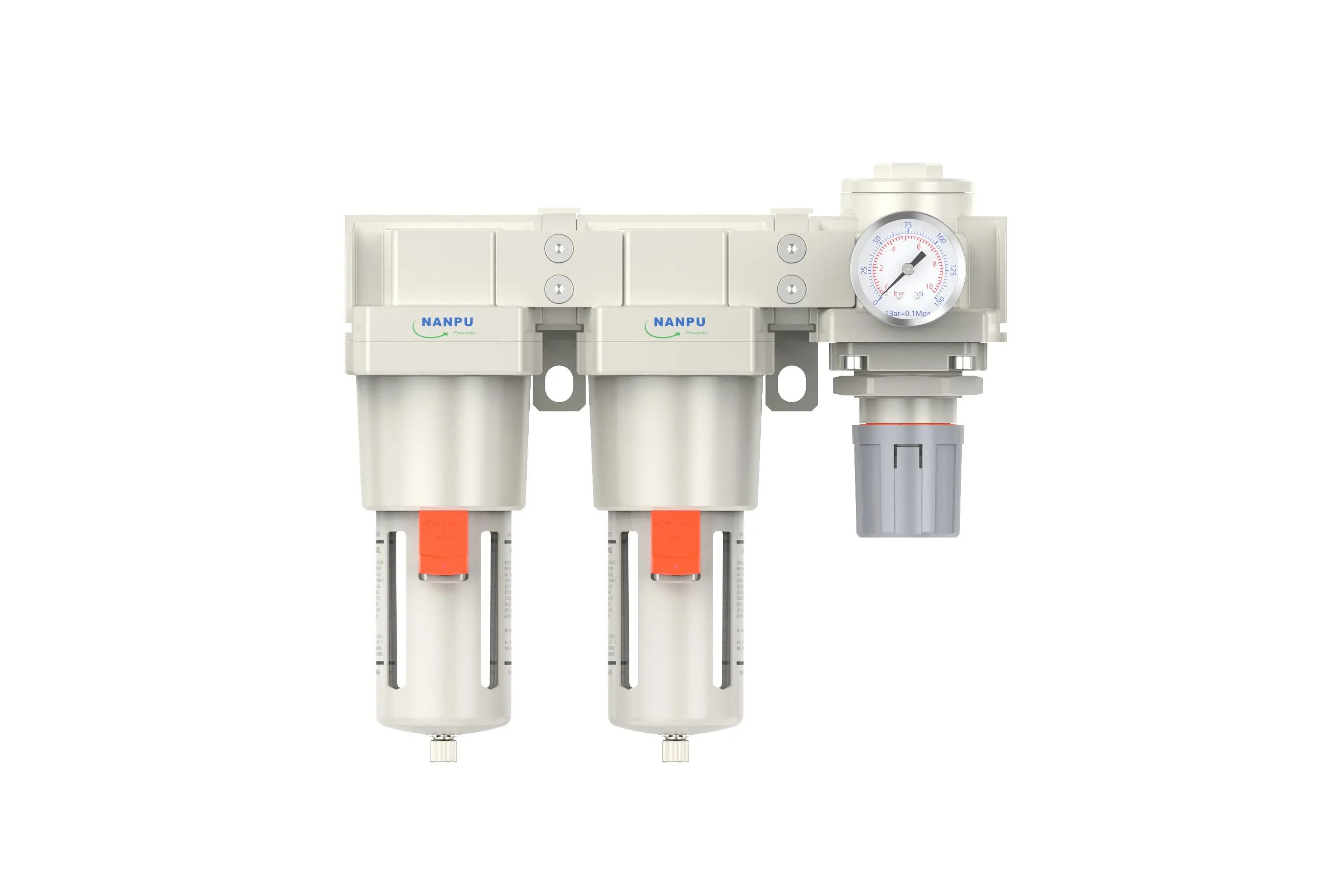
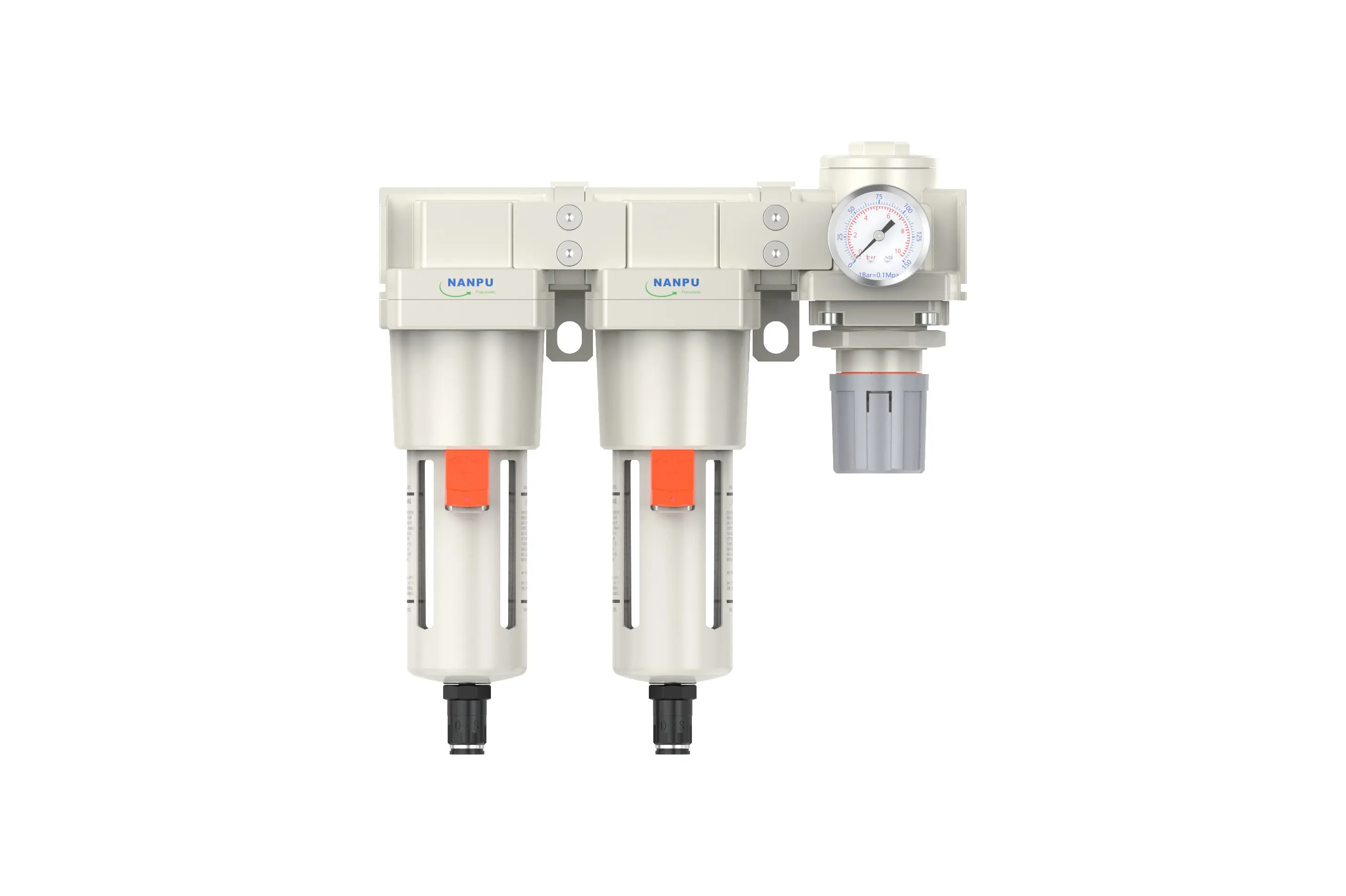
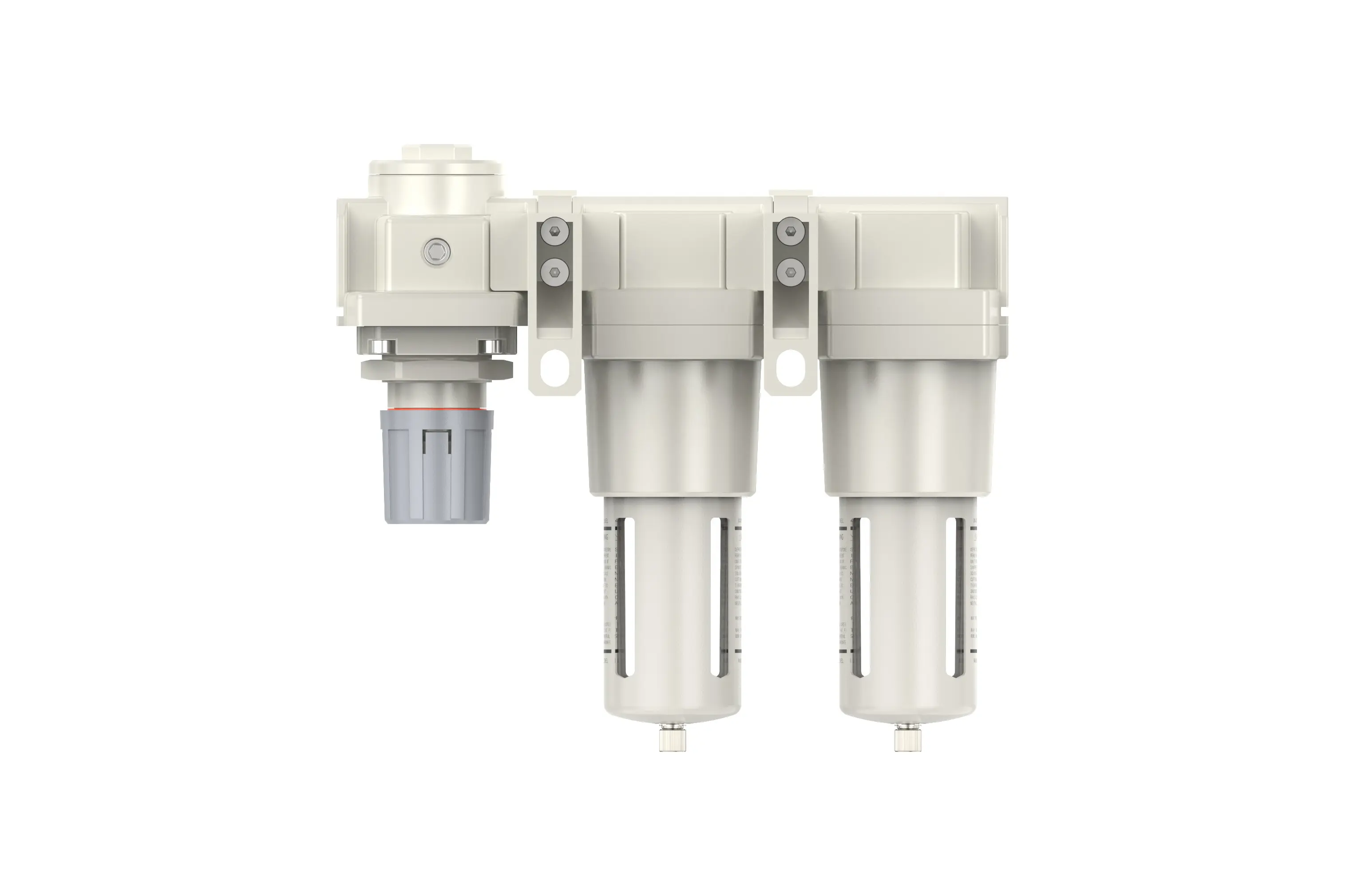
Manual Drain DFR-10 1"
Auto Drain DFR-10-D 1"
NANPUDFR-10 1" DFR Air Drying System
| DFR | 5000 | 10 | BSP | D |
| Series Number | Body Size | Port Size | Thread Type | Drainage Method |
| 2000 | 02:1/4" | BSP | Blank: Differential Pressure Drain | |
| 3000 | 03:3/8" | NPT | A: Manual Drain | |
| 4000 | 04:1/2" | PT | D: Auto Drain | |
| 4000/5000 | 06: 3/4" | |||
| 5000 | 10: 1" |
NANPUTechnical Specifications
| Model | Model | |
| Manual Drain | Auto Drain | (L/min)Rated Flow Rate |
| DFR2000-02 | DFR2000-02D | 500 |
| DFR3000-02 | DFR3000-02D | 2000 |
| DFR3000-03 | DFR3000-03D | 2000 |
| DFR4000-04 | DFR4000-04D | 4000 |
| DFR4000-06 | DFR4000-06D | 4500 |
| DFR5000-06 | DFR5000-06D | 5000 |
| DFR5000-10 | DFR5000-10D | 5000 |
| Max Input Pressure | 1.2Mpa{12.24kgf/cm²} /174.04Psi |
| Max Operating Pressure | 1.0Mpa{10.2kgf/cm²} /145Psi |
| Temperature Range | 5~60℃ |
| Filtration Accuracy | 0.01μm, 5μm, 40μm |
| Bowl Material | Polycarbonate |
| Bowl Guard | AC2000(None) AC3000~5000(YES) |
| Pressure Range | AC2000~5000/0.05~0.85Mpa(0.51~8.7kgf/cm² )/0~125Psi |
1. Preparation
All calibration components must adhere to the maximum flow rate requirements.
Prior to installation, meticulously clean all ports and fittings to prevent dust ingress into the air passage.
Verify that the air flow direction corresponds with the arrow markings on the product body, and ensure that port and thread dimensions are compatible.
2. Pressure Adjustment
Lift the pressure gauge knob and then rotate it:
Rotating the knob clockwise will gradually increase the pressure, while a counter - clockwise rotation will decrease it.
Once the desired pressure reading is reached, halt the rotation and firmly lock the knob. Failing to perform this step may result in pressure leakage.
3. Dial Reading
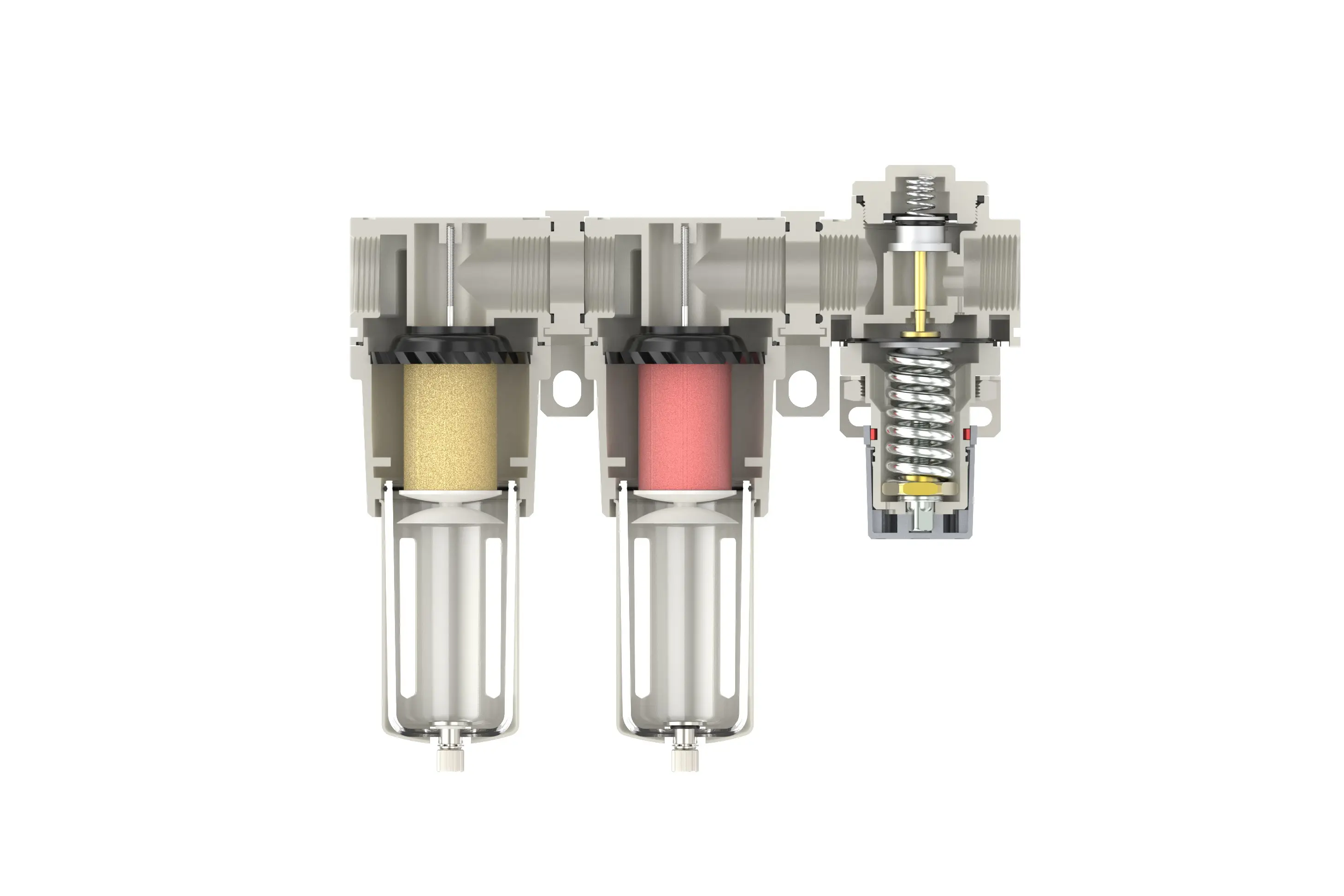
5 - Micron Brass Filter Element: Exhibits exceptional filtration efficiency, extended operational lifespan, and recyclability.
0.5 and 0.01 - Micron Filter Elements: Efficiently eliminate minute contaminants.
The drain valve operates automatically. It opens in the absence of pressure and closes when air is flowing. When the water level exceeds the maximum allowable level, immediate drainage is imperative; otherwise, dehumidification performance will be significantly degraded.
4. Drainage
The drain valve automatically activates in the absence of pressure to expel condensate and closes during air flow. When the water level exceeds the designated maximum, prompt drainage is required; failure to do so will result in suboptimal dehumidification performance.
The connector on the drain assembly is designed for air hose attachment and can be easily detached as per operational requirements.
Use a wrench to tighten all fittings to prevent leakage. During initial installation, a release of air may occur, which is not a leak. This phenomenon is due to the pressure differential between the internal system and the external environment, necessitating the expulsion of excess air. In such situations, allow sufficient time for the system to stabilize, after which it will operate normally.