


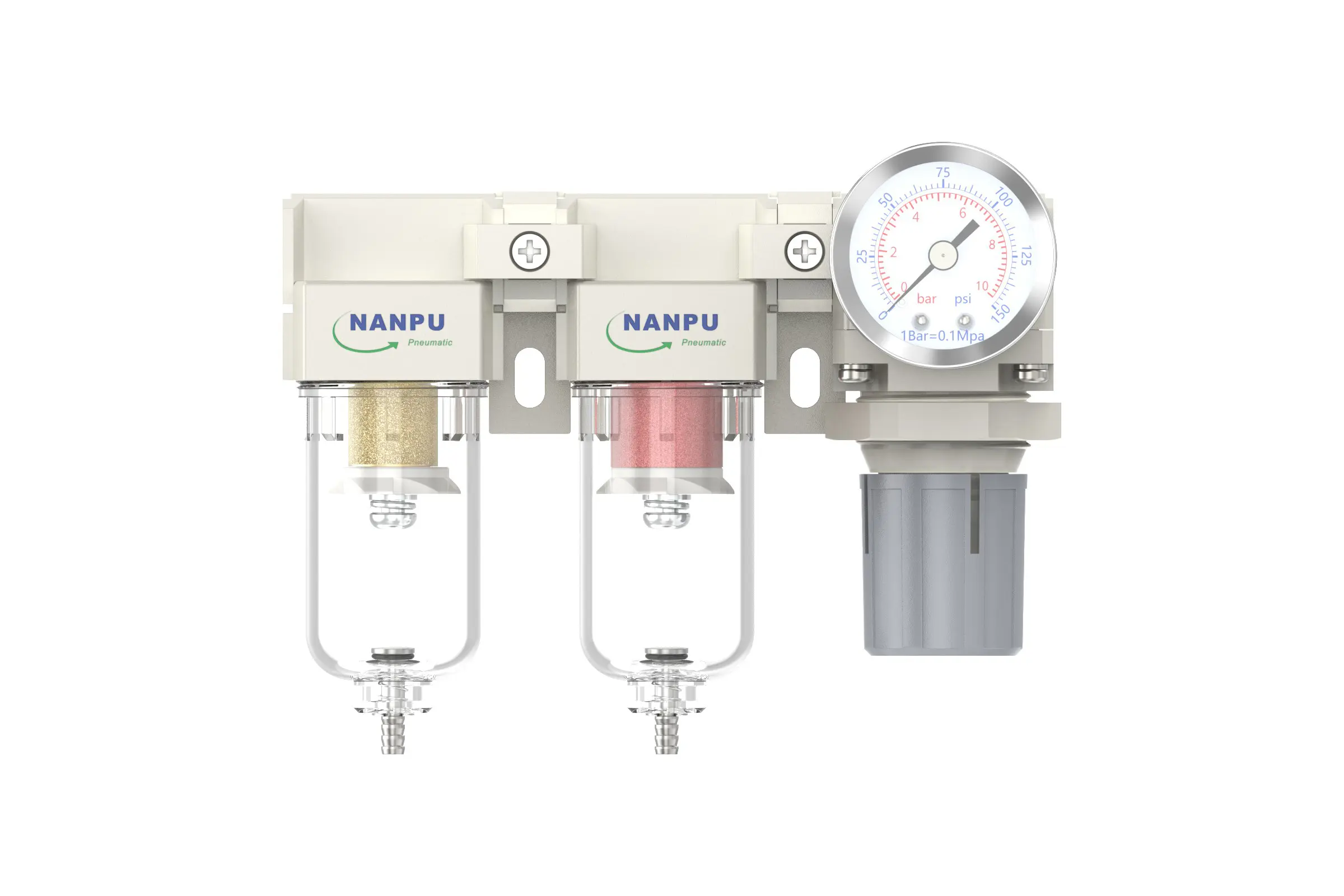
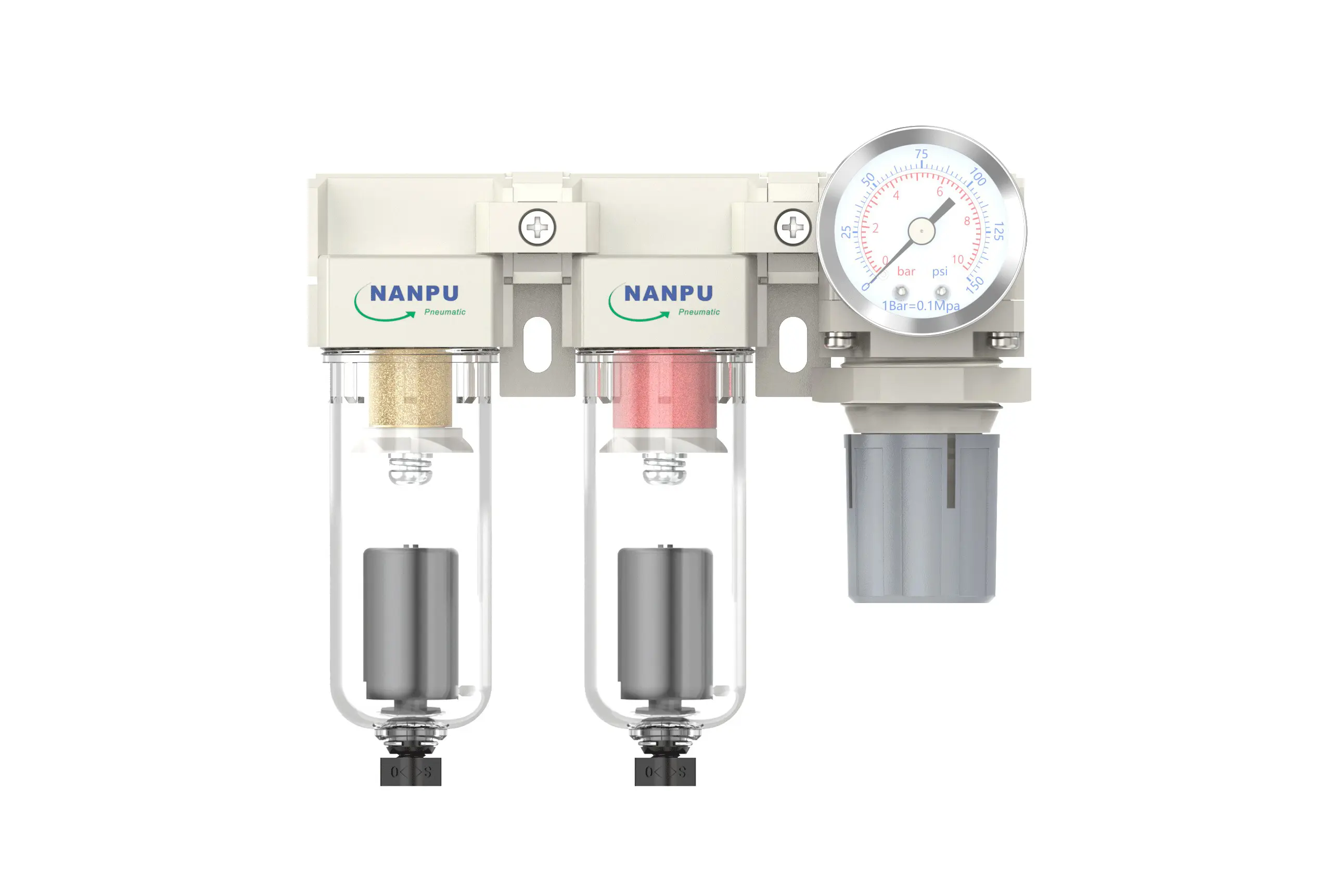
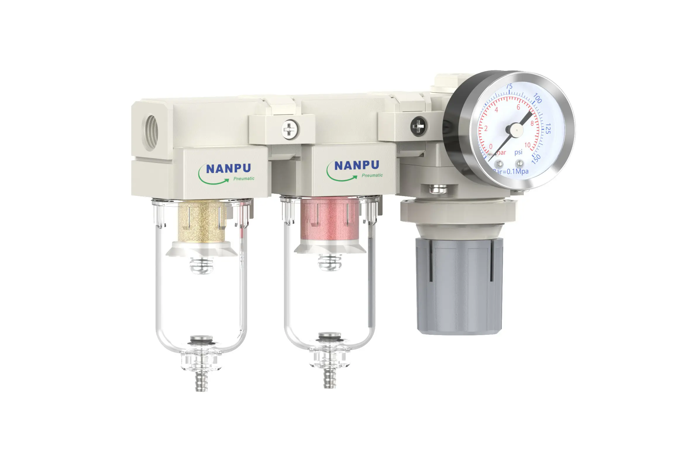
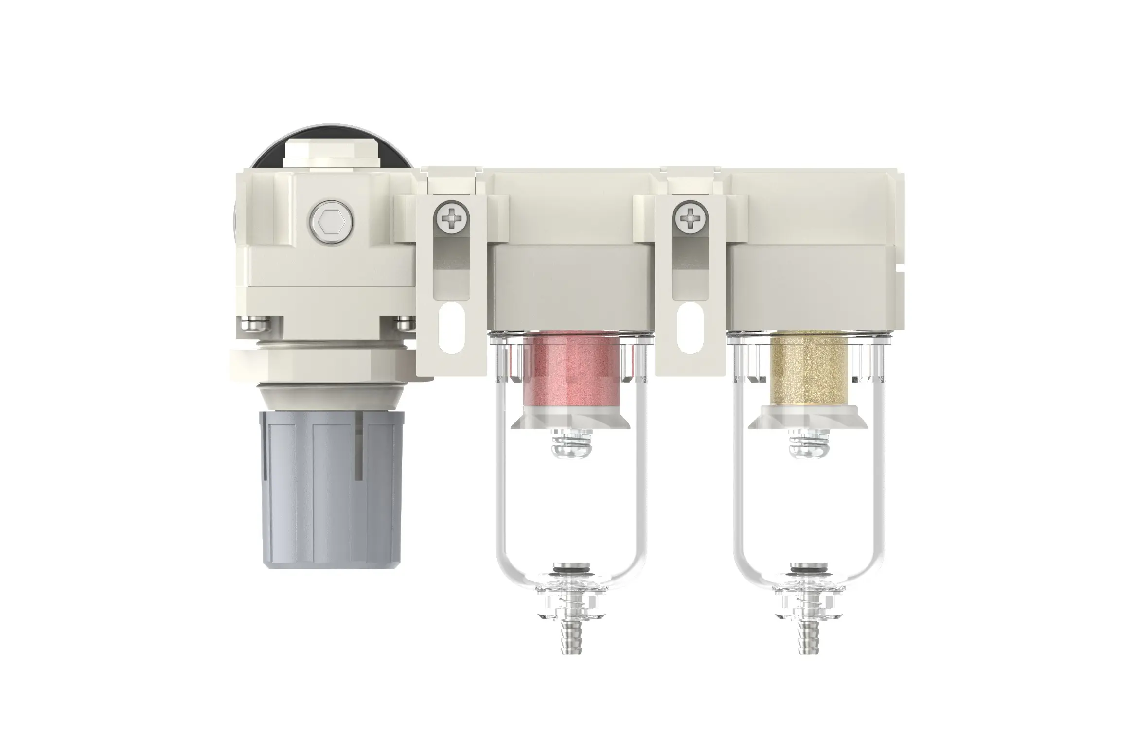
DFR-02 1/4" DFR Air Drying System
description1
DFR-02 1/4" DFR Air Drying System
Manual Drain DFR-02 1/4" Portsize:1/4" Air Drying System
Auto Drain DFR-02D 1/4" Portsize:1/4" Air Drying System
NANPUDFR-02 1/4" DFR Air Drying System
| DFR | 2000 | 02 | BSP | D |
| Series Number | Body Size | Port Size | Thread Type | Drainage Method |
| 2000 | 02:1/4" | BSP | Blank: Differential Pressure Drain | |
| 3000 | 03:3/8" | NPT | A: Manual Drain | |
| 4000 | 04:1/2" | PT | D: Auto Drain | |
| 4000/5000 | 06: 3/4" | |||
| 5000 | 10: 1" |
NANPUTechnical Specifications
| Model | Model | |
| Manual Drain | Auto Drain | (L/min)Rated Flow Rate |
| DFR2000-02 | DFR2000-02D | 500 |
| DFR3000-02 | DFR3000-02D | 2000 |
| DFR3000-03 | DFR3000-03D | 2000 |
| DFR4000-04 | DFR4000-04D | 4000 |
| DFR4000-06 | DFR4000-06D | 4500 |
| DFR5000-06 | DFR5000-06D | 5000 |
| DFR5000-10 | DFR5000-10D | 5000 |
| Max Input Pressure | 1.2Mpa{12.24kgf/cm²} /174.04Psi |
| Max Operating Pressure | 1.0Mpa{10.2kgf/cm²} /145Psi |
| Temperature Range | 5~60℃ |
| Filtration Accuracy | 0.01μm, 5μm, 40μm |
| Bowl Material | Polycarbonate |
| Bowl Guard | AC2000(None) AC3000~5000(YES) |
| Pressure Range | AC2000~5000/0.05~0.85Mpa(0.51~8.7kgf/cm² )/0~125Psi |
1. Preparation
Every calibration part must adhere to the maximum flow rate standards.
Before installation, meticulously scrub all ports and connectors to stop dust from entering the air pathway.
Make sure that the air flow orientation matches the arrow signs on the product casing, and check that port and thread sizes are consistent.
2. Pressure Adjustment
Lift the knob and then start turning it. Turning it in a clockwise direction will steadily raise the pressure, whereas turning it counterclockwise will lower it. After attaining the target pressure level, stop turning and firmly push down the knob. Not carrying out this procedure might lead to pressure seepage.
3. Dial Reading
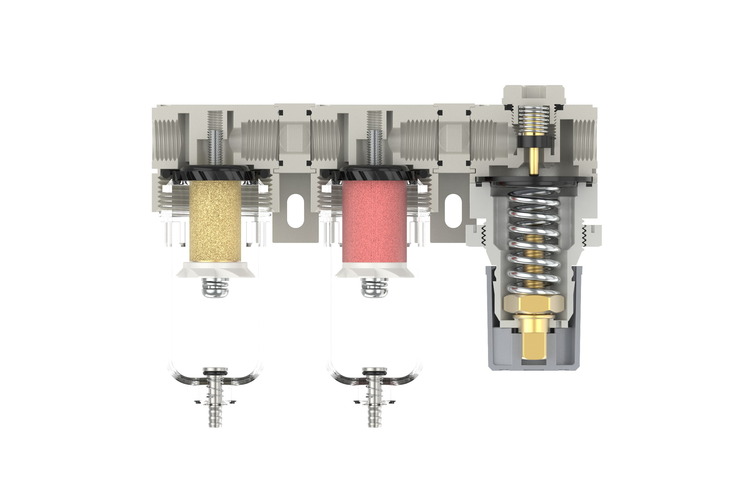
5-micron Brass Filter Element: Demonstrates excellent filtering effectiveness, prolonged operational lifespan, and can be reused.
0.5-micron and 0.01-micron Filter Elements: Efficiently eliminate tiny impurities.
The drainage valve functions autonomously. It activates to discharge when pressure is absent and seals when air passes through. When the water level surpasses the set upper limit, immediate manual drainage is necessary. Neglecting this may cause reduced dehumidification efficiency.
4. Drainage
The drain valve functions in an automated manner. It unlocks when there is no pressure and shuts during air circulation. Once the water level hits or exceeds the maximum limit, prompt draining is essential; failing to do so will greatly reduce dehumidification performance.
The fitting on the drain unit serves as a connection for an air hose. It can be readily removed according to particular operating needs.
Employ a spanner to firmly fasten all connectors to avoid seepage. When initially installing, a transient escape of air might happen. This is not a leak; instead, it stems from the internal pressure difference compared to the external surroundings, requiring the release of surplus air. In these cases, give a short interval for the system to settle, after which it will function as usual.