


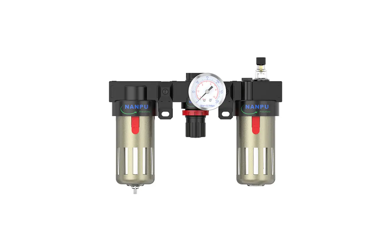
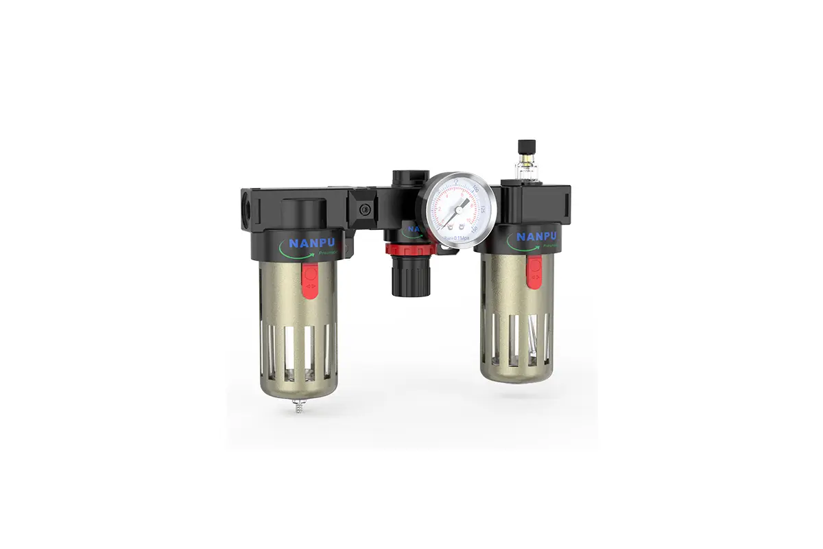
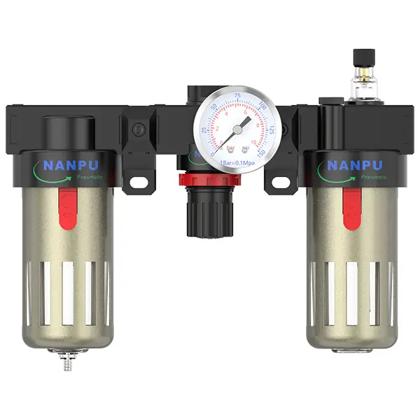
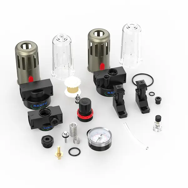
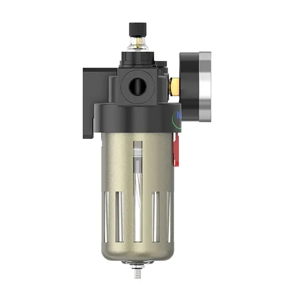
BC2000/BC3000/BC4000 1/4" 3/8" 1/2" F.R.L.Combination Air Filter, Regulator & Lubricator
description1
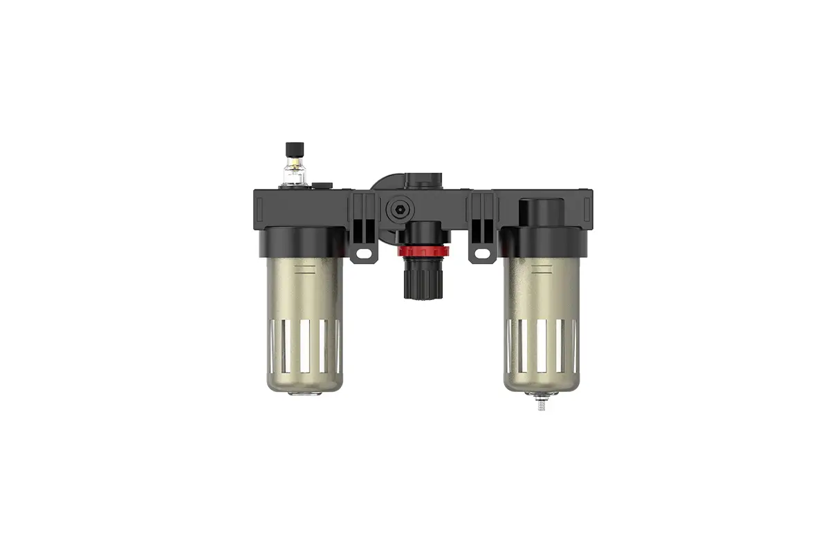
BFC2000/BFC3000/BFC4000
Manual Drain BFC2000/BFC3000/BFC4000 1/4" 3/8" 1/2" F.R.L.Combination Air Filter, Regulator & Lubricator"
Auto Drain BFC2000-D/BFC3000-D/BFC4000-D 1/4" 3/8" 1/2" F.R.L.Combination Air Filter, Regulator & Lubricator"
NANPUBC2000/BC3000/BC4000 1/4" 3/8" 1/2" F.R.L.Combination Air Filter, Regulator & Lubricator"
| BC | 2000 | BSP | D | |
| Series Number | Body Size | Port Size | Thread Type | Drainage Method |
| 2000 | 02: 1/4" | BSP | Blank: Differential Pressure Drain | |
| 3000 | 03: 3/8" | NPT | A: Manual Drain | |
| 4000 | 04: 1/2" | PT | D: Auto Drain |
NANPUTechnical Specifications
| Parameter | Value |
| Max Input Pressure | 1.0Mpa(10.2kgf/cm²) 145Psi |
| Max Operating Pressure | 1.0Mpa(10.2kgf/cm²) 145Psi |
| Temperature Range | 5-60℃ |
| Filtration Accuracy | 5μm、40μm |
| Bowl Material | Polycarbonate |
| Bowl Guard | AFC2000 (None) BFC2000-4000 (YES) |
| Suggested Oil | Turbine Oil No. 1 ISO-VG32 |
| Pressure Range | AC/BC 0.05-0.85Mpa (0.51-8.7kgf/cm²) 0-125Psi |
| Model Manual Drain |
Model Auto Drain |
(L/min) Rated Flow Rate |
| AC2000 | AC2000-D | 650 |
| BC2000 | BC2000-D | 1400 |
| BC3000 | BC3000-D | 1400 |
| BC4000 | BC4000-D | 1400 |
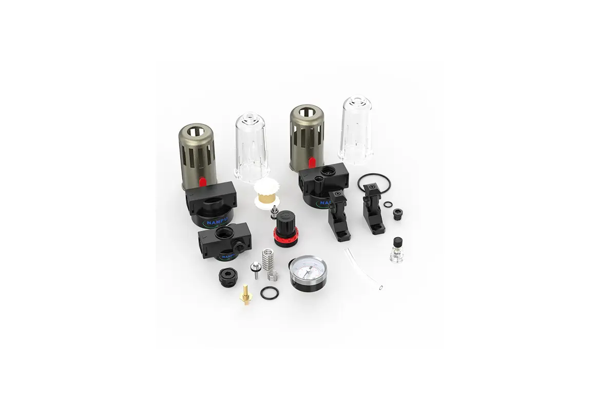
| Product Benefits |
| All Portsize Piggyback Air Filter (5 Micron Element,Standard) Regulator & Lubricator (FRL) |
| Dry Air, Pressure Regulating & Lubricate Air |
| Temperature Range: 41~140°F (5~60°C) |
NANPU Installation and Operating
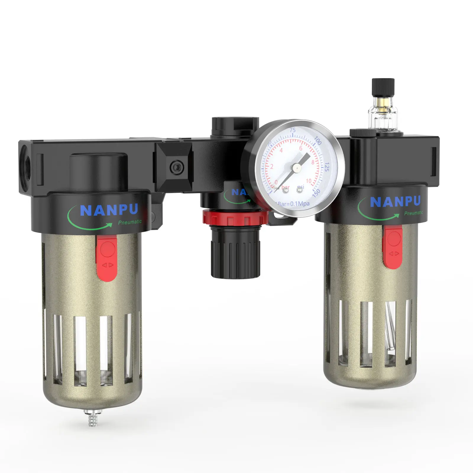
2. Pressure Adjustment Elevate the pressure gauge knob and initiate rotation: Clockwise rotation shall gradually increase pressure in a uniform manner, while counterclockwise rotation will effect a decrease. Cease rotation once the target pressure is achieved, then firmly depress the knob. Failure to secure the knob may result in pressure leakage issues.
3. Dial Reading
Ensure the pressure gauge is securely mounted to the main structure. During pressure adjustment, monitor the gauge closely to verify that the readings increase and decrease uniformly.
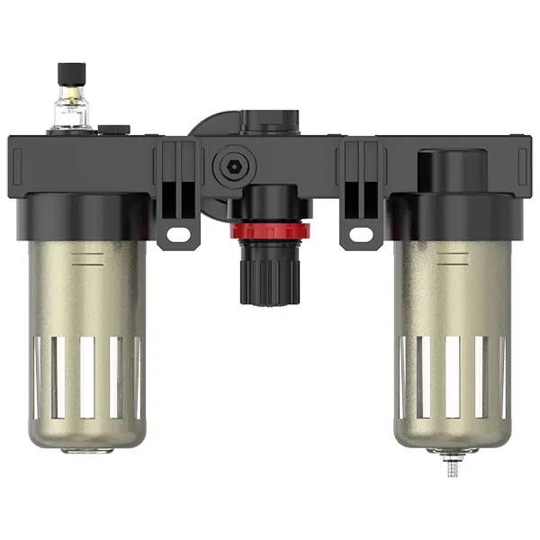
4. Drainage
The drainage valve operates in an automatic mode. In the absence of pressure, it unlocks to discharge moisture and seals when air flow is initiated. When the water level reaches or exceeds the allowable maximum, immediate drainage is necessary; otherwise, dehumidification efficiency will be reduced. The fitting on the drainage unit is designed for connecting an air hose and can be easily detached as per specific operational requirements.
5. Oil Adjustment
Rotate the metering valve clockwise to increase the lubricant intake rate. Conversely, counterclockwise rotation of the metering valve will reduce the intake rate or halt it entirely.
6. Refueling
Rotate the filler screw clockwise. The volume of lubricant introduced must not exceed 80% of the container's rated capacity. Upon completion of the refilling process, ensure the filler screw is securely tightened.