


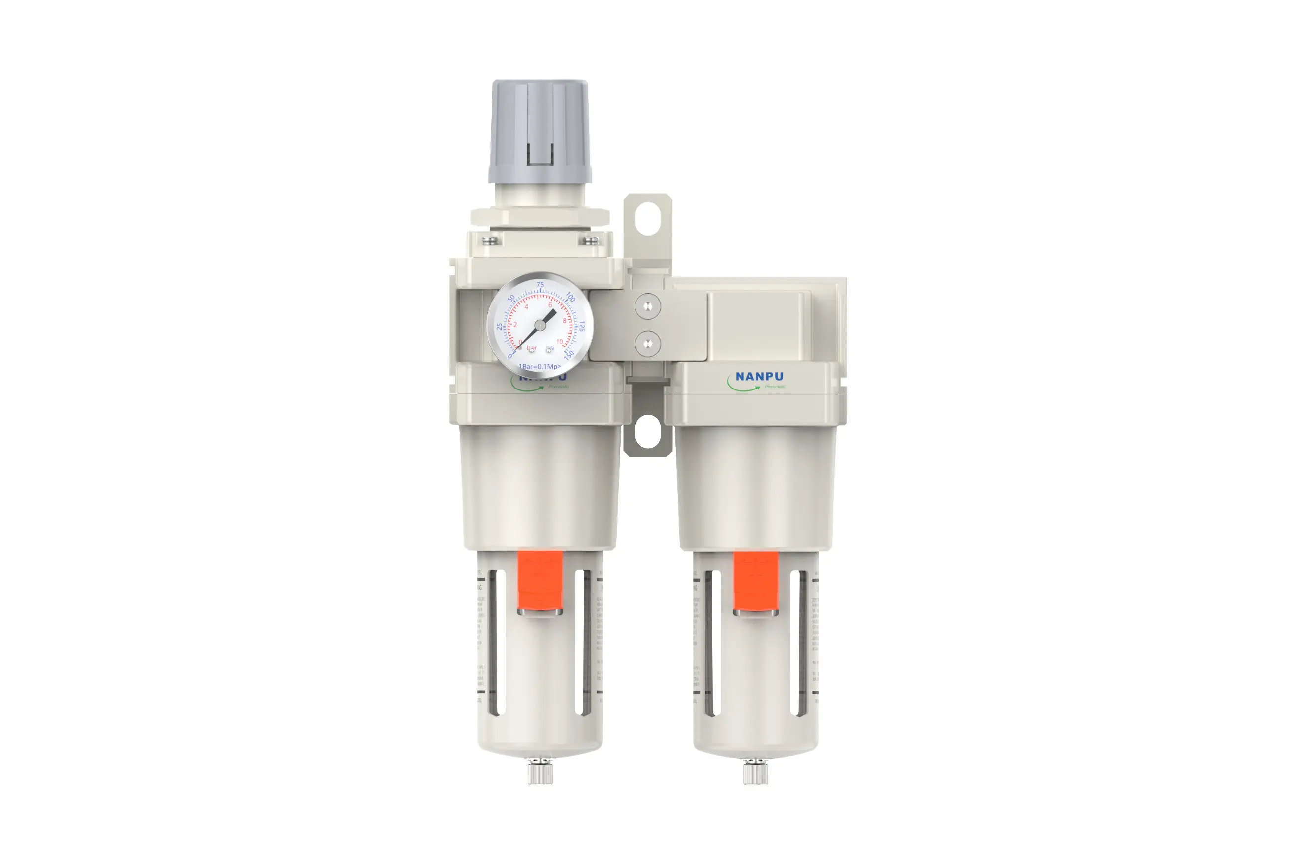
AWF5010-06/AWF5010-10 1"AWFF Air Drying System Manual Drain&Auto Drain
description1
AWF5010-06/AWF5010-10
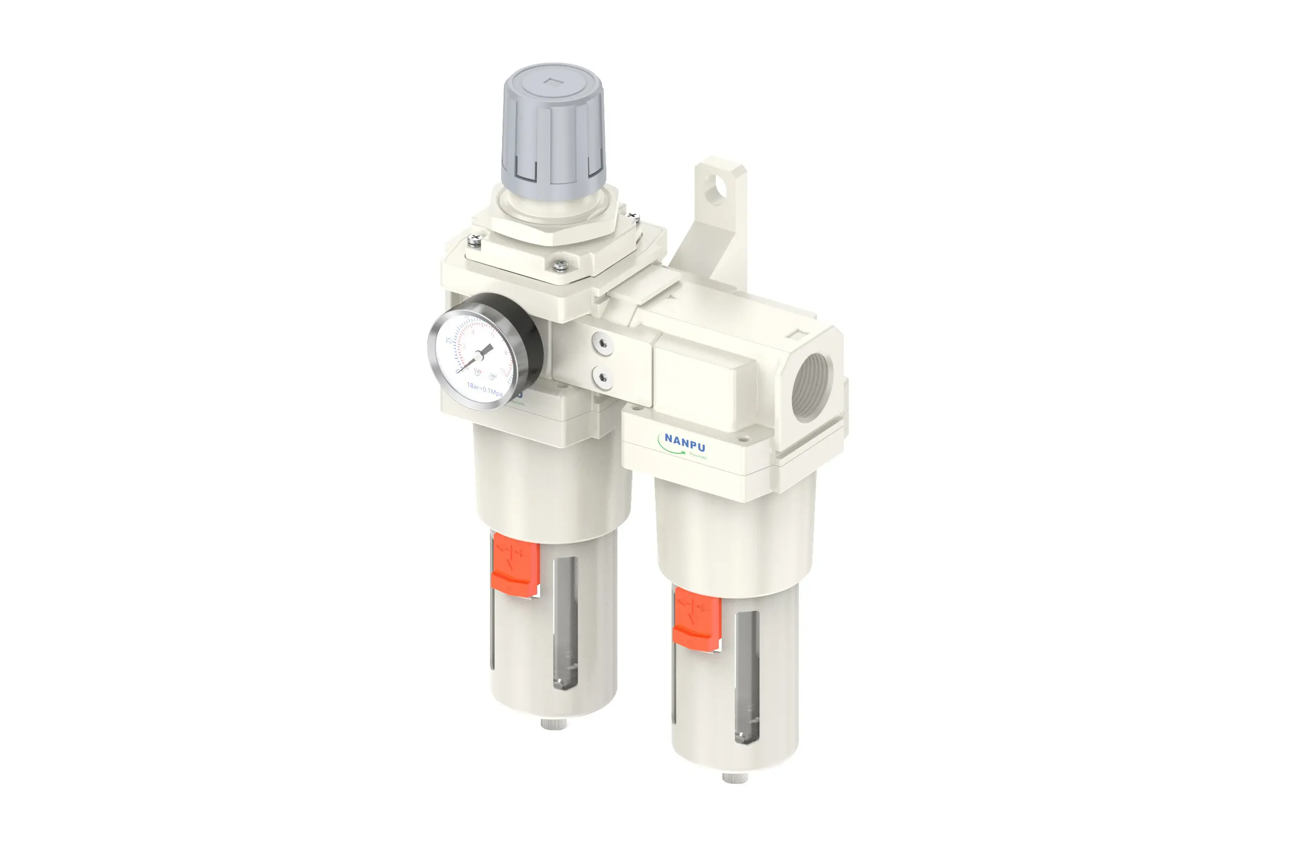
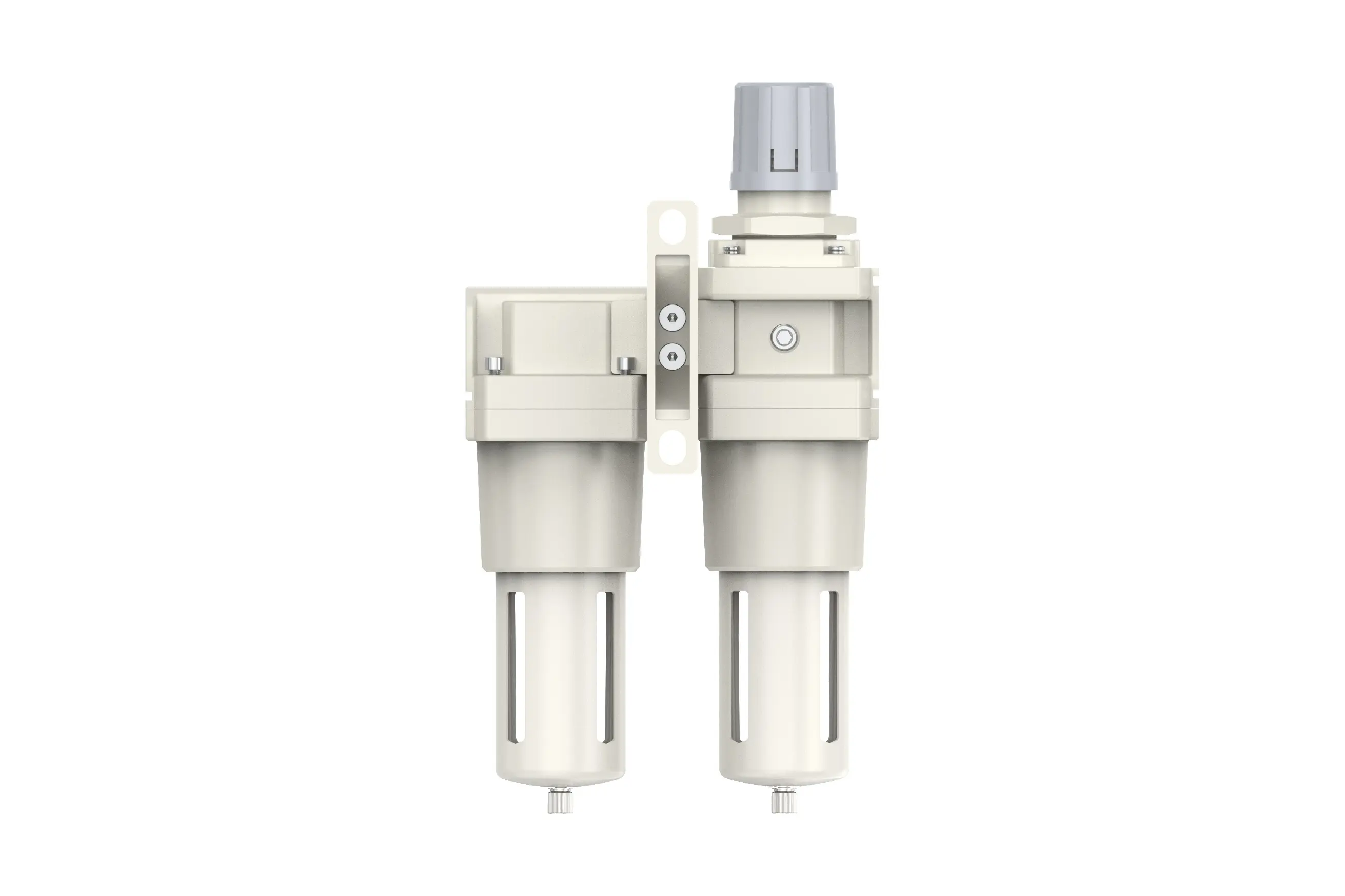
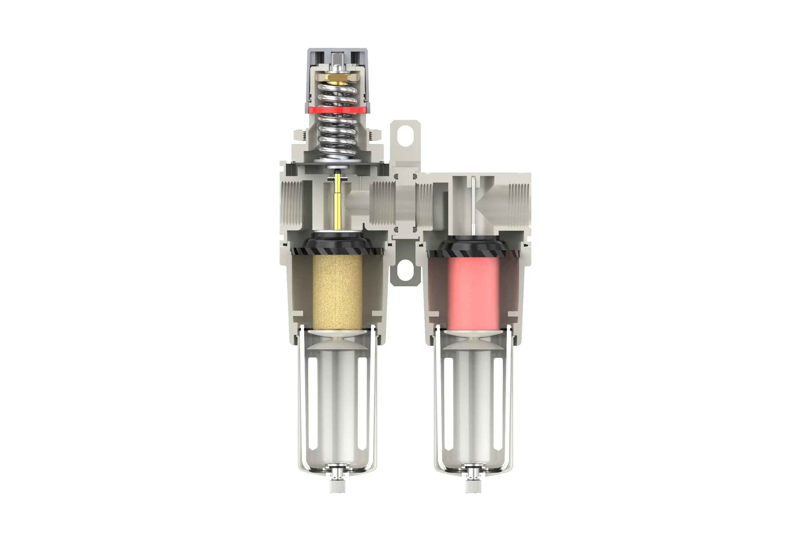
Manual Drain AWF5010-06/AWF5010-10 Portsize:1" Air Drying System
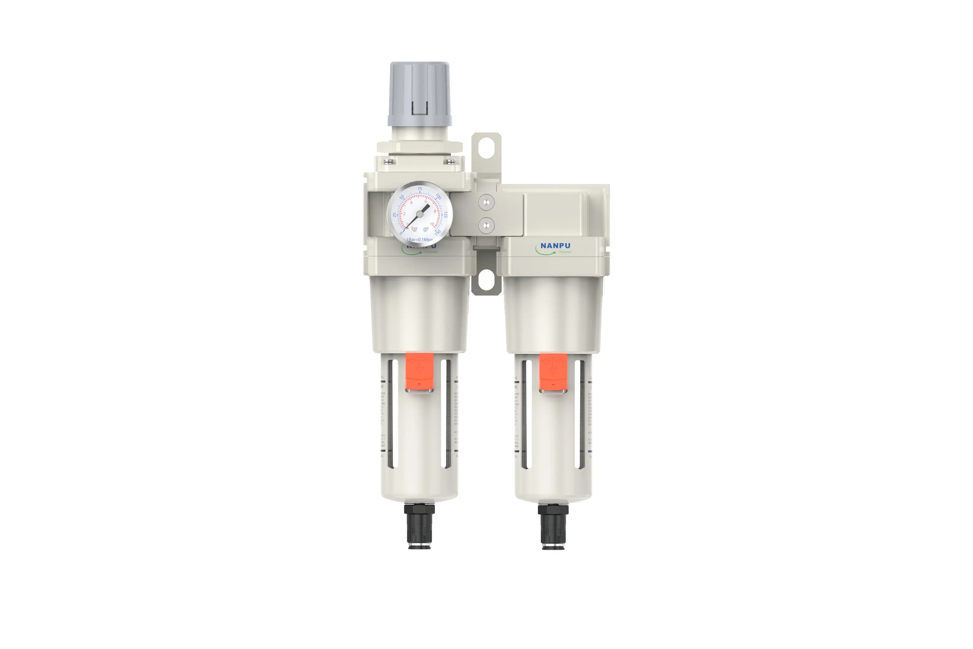
Auto Drain AWF5010-06D/AWF5010-10D Portsize:1" Air Drying System
NANPUAWF5010-06/AWF5010-10
| AWF | 2010 | 02 | BSP | D |
| Series Number | Body Size | Port Size | Thread Type | Drainage Method |
| 2000 | 02:1/4" | BSP | Blank: Differential Pressure Drain | |
| 3000 | 03:3/8" | NPT | A: Manual Drain | |
| 4000 | 04:1/2" | PT | D: Auto Drain | |
| 4000/5000 | 06: 3/4" | |||
| 5000 | 10: 1" |
NANPUTechnical Specifications
| Model | Model | |
| Manual Drain | Auto Drain | (L/min)Rated Flow Rate |
| AWF2010-02 | AWF2010-02D | 500 |
| AWF3010-02 | AWF3010-02D | 2000 |
| AWF3010-03 | AWF3010-03D | 2000 |
| AWF4010-04 | AWF4010-04D | 4000 |
| AWF4010-06 | AWF4010-06D | 4500 |
| AWF5010-06 | AWF5010-06D | 5000 |
| AWF5010-10 | AWF5010-10D | 5000 |
| Max Input Pressure | 1.2Mpa{12.24kgf/cm²} /174.04Psi |
| Max Operating Pressure | 1.0Mpa{10.2kgf/cm²} /145Psi |
| Temperature Range | 5~60℃ |
| Filtration Accuracy | 0.01μm, 5μm, 40μm |
| Bowl Material | Polycarbonate |
| Bowl Guard | AC2000(None) AC3000~5000(YES) |
| Pressure Range | AC2000~5000/0.05~0.85Mpa(0.51~8.7kgf/cm² )/0~125Psi |
1. Preparation
All calibration assemblies must adhere to the maximum flow rate specifications.
Prior to installation, meticulously clean the ports and fittings to prevent dust contamination of the air pathway.
Verify that the air flow direction corresponds to the arrow markings on the product body, and ensure that the port and thread dimensions are properly matched.
2. Pressure Adjustment
Elevate the pressure gauge knob and rotate it as follows:
A clockwise rotation will cause the pressure to increase in a stable manner, while a counterclockwise rotation will result in a decrease in pressure.
Once the desired pressure value is achieved, cease rotation and firmly secure the knob. Failure to perform this locking step may lead to potential leakage issues.
3. Dial Reading
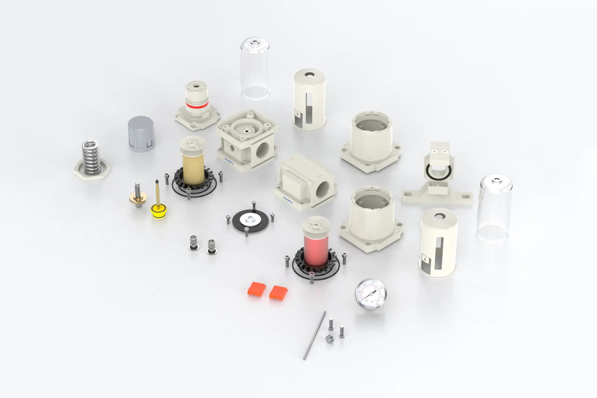
5-Micron Brass Filter Element: Boasts exceptional filtration capabilities, significantly extended service life, and offers the possibility of reuse.
0.5 and 0.01-Micron Filter Elements: Efficiently remove minute impurities from the medium.
The drainage column operates automatically. It opens to discharge when pressure is absent and closes upon the passage of airflow. When the water level exceeds the upper limit, immediate drainage is imperative; failure to do so will lead to suboptimal dehumidification performance.
4. Drainage
The drainage column is designed for automatic operation. It will open to discharge when pressure is absent and close upon the passage of airflow. When the water level reaches or exceeds the upper - limit threshold, prompt drainage is required; otherwise, dehumidification efficiency will be significantly compromised.
The fitting on the drain head is intended for air hose connection and can be detached as per specific operational requirements.
Utilize an appropriate wrench to torque the fittings securely, thereby preventing any potential leakage. During the initial installation, an air expulsion phenomenon may occur. This is not a leakage; rather, it is a result of the pressure differential between the internal and external environments, necessitating the release of excess air. In such situations, allow the system sufficient time to stabilize, after which it will operate normally.