


AWF2010-02/AWF2010-02D 1/4" AWFF Air Drying System
description1
AWF2010-02/AWF2010-02D
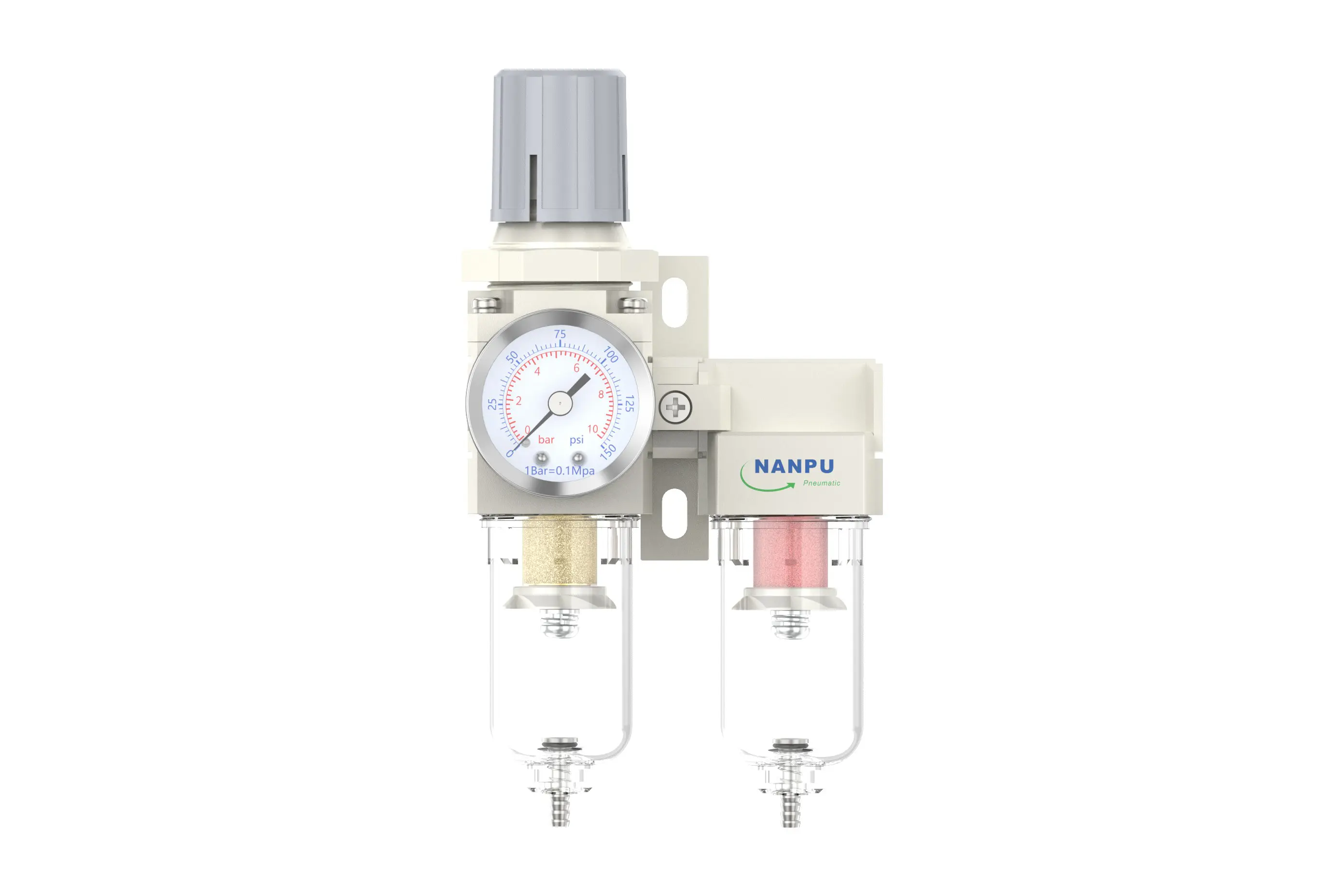
Manual Drain AWF2010-02 Portsize:1/4" Air Drying System
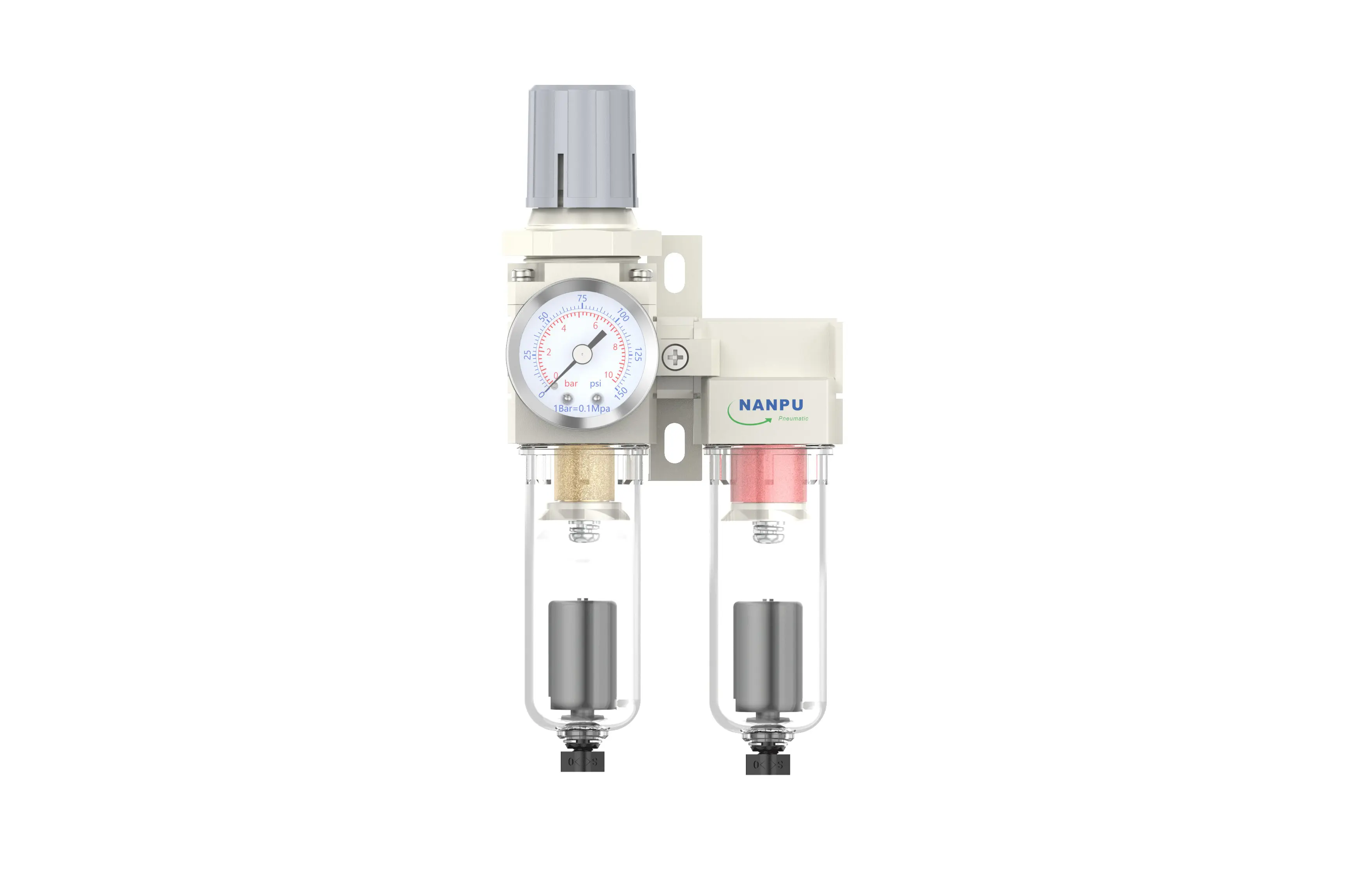
Auto Drain AWF2010-02D Portsize:1/4" Air Drying System
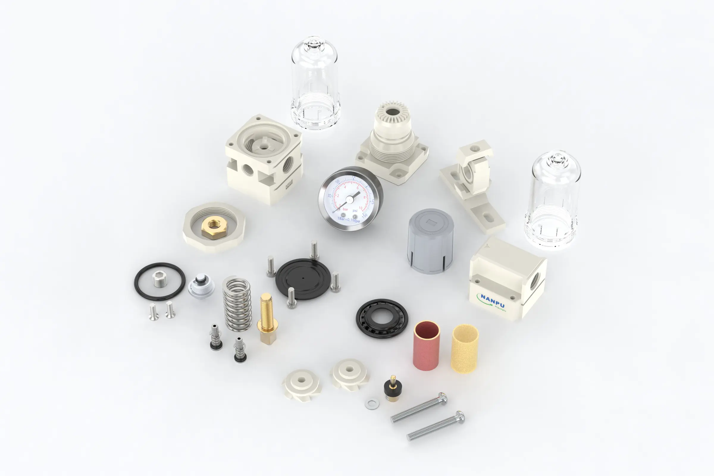
NANPUAWF2010-02/AWF2010-02D 1/4" AWF Air Drying System
| AWF | 2010 | 02 | BSP | D |
| Series Number | Body Size | Port Size | Thread Type | Drainage Method |
| 2000 | 02:1/4" | BSP | Blank: Differential Pressure Drain | |
| 3000 | 03:3/8" | NPT | A: Manual Drain | |
| 4000 | 04:1/2" | PT | D: Auto Drain | |
| 4000/5000 | 06: 3/4" | |||
| 5000 | 10: 1" |
NANPUTechnical Specifications
| Model | Model | |
| Manual Drain | Auto Drain | (L/min)Rated Flow Rate |
| AWF2010-02 | AWF2010-02D | 500 |
| AWF3010-02 | AWF3010-02D | 2000 |
| AWF3010-03 | AWF3010-03D | 2000 |
| AWF4010-04 | AWF4010-04D | 4000 |
| AWF4010-06 | AWF4010-06D | 4500 |
| AWF5010-06 | AWF5010-06D | 5000 |
| AWF5010-10 | AWF5010-10D | 5000 |
| Max Input Pressure | 1.2Mpa{12.24kgf/cm²} /174.04Psi |
| Max Operating Pressure | 1.0Mpa{10.2kgf/cm²} /145Psi |
| Temperature Range | 5~60℃ |
| Filtration Accuracy | 0.01μm, 5μm, 40μm |
| Bowl Material | Polycarbonate |
| Bowl Guard | AC2000(None) AC3000~5000(YES) |
| Pressure Range | AC2000~5000/0.05~0.85Mpa(0.51~8.7kgf/cm² )/0~125Psi |
1. Preparation
All calibration assemblies must satisfy the maximum flow rate requirements.
Prior to installation, thoroughly clean the ports and fittings to prevent the ingress of dust into the air passage.
Verify that the direction of the air flow corresponds to the arrow markings on the product body. Additionally, ensure that the port and thread dimensions are compatible.
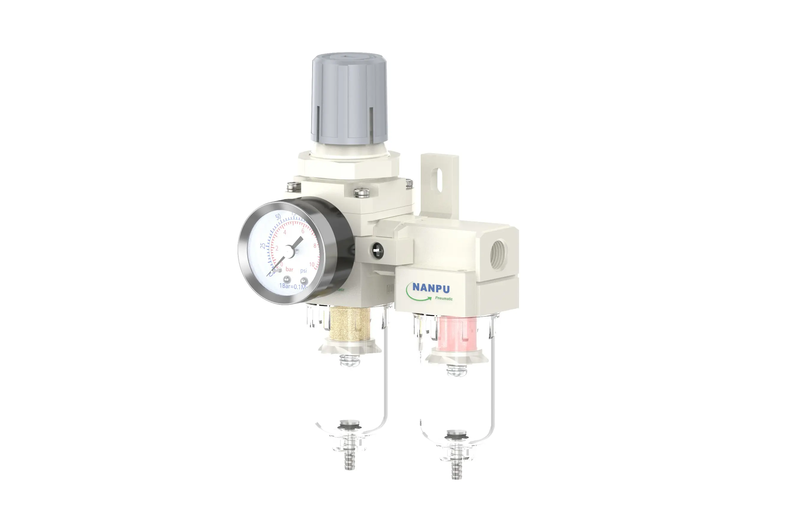
2. Pressure Adjustment
Elevate the pressure gauge knob and initiate rotation. A clockwise rotation will result in a consistent increase in pressure, whereas a counterclockwise rotation will cause the pressure to decrease. Upon achieving the desired pressure value, cease rotation and secure the knob. Failure to lock the knob may lead to potential leakage issues.
3. Dial Reading
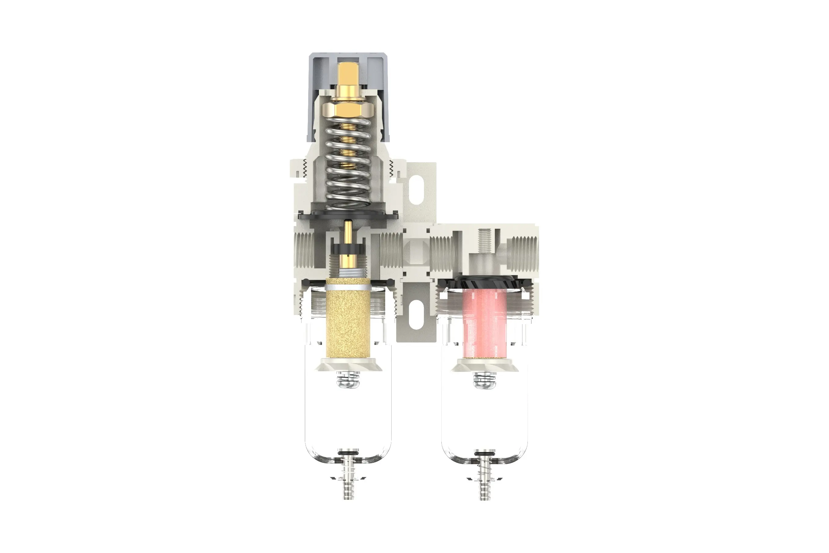
5 Micron Brass Filter Element: Exhibits superior filtration efficiency, extended service life, and is designed for reuse.
0.5 and 0.01 Micron Filter Elements: Capable of efficiently removing minute impurities from the fluid stream.
The drainage column operates in an automated fashion. It opens to discharge when pressure is absent and closes upon the passage of airflow. In the event that the water level exceeds the designated upper limit, immediate drainage is required; failure to do so will compromise dehumidification performance.
4. Drainage
The drainage column functions automatically, opening to discharge when pressure is not present and closing upon the passage of airflow. When the water level surpasses the upper threshold, immediate drainage is essential; failure to do so will result in subpar dehumidification performance. The fitting on the drain head is designed for air hose connection and can be detached as per operational requirements.
Utilize an appropriate wrench to securely tighten all fittings to prevent leakage. During the initial installation, an expulsion process may occur (this is not a leakage; rather, due to the initial disparity between internal and external pressures, it is necessary to release excess air). In such instances, allow sufficient time for the system to stabilize, after which it will operate optimally.