


AW5000-06AW5000-10 AW Filter Regulator
description1
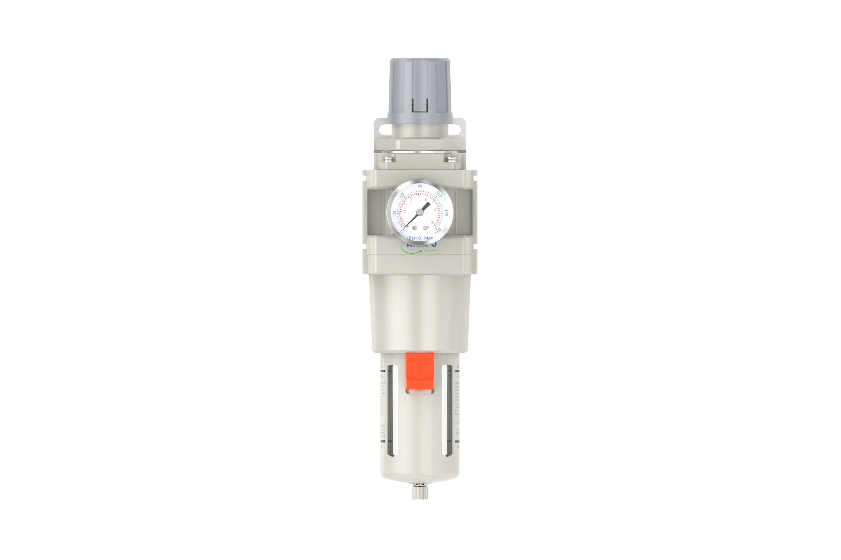
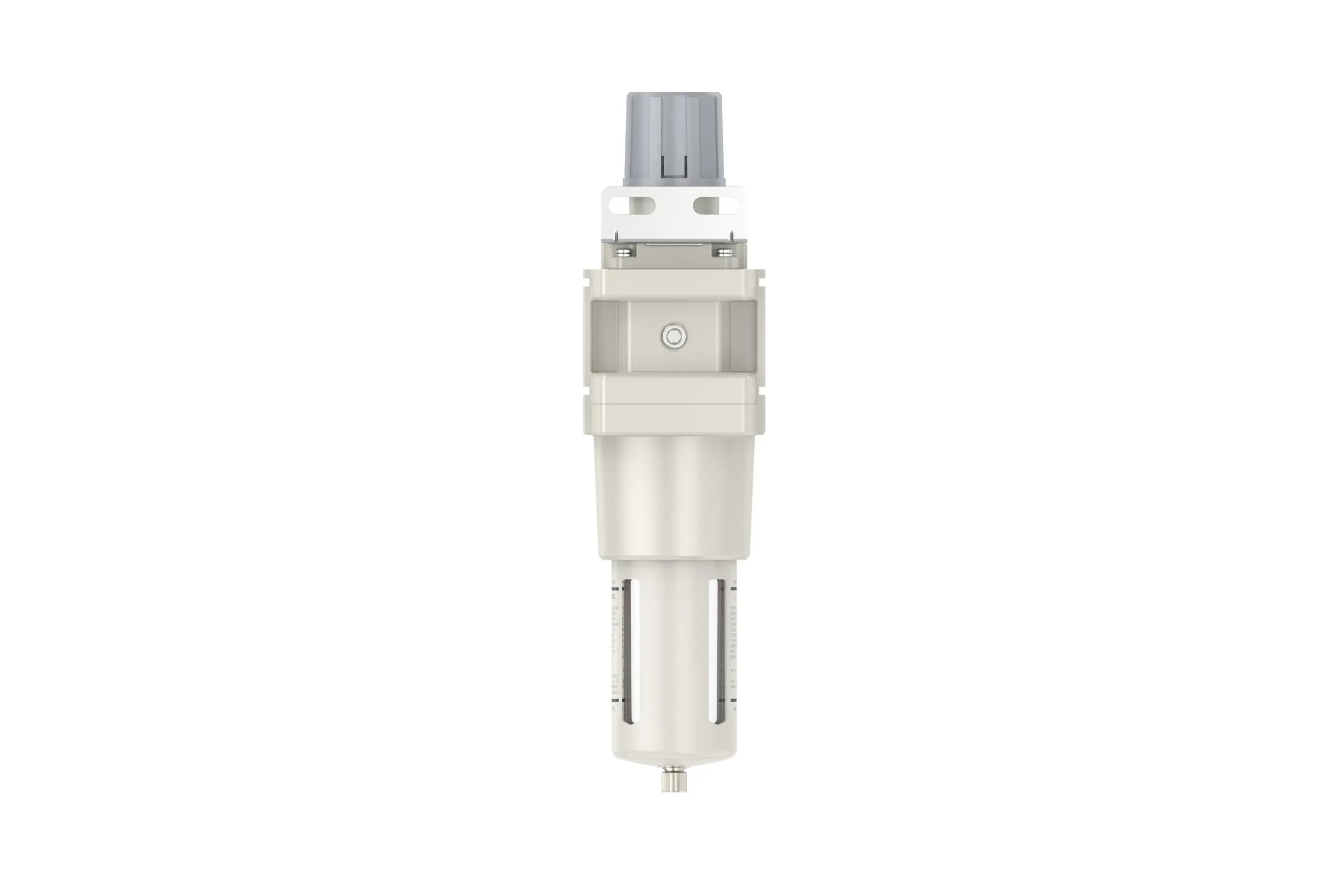
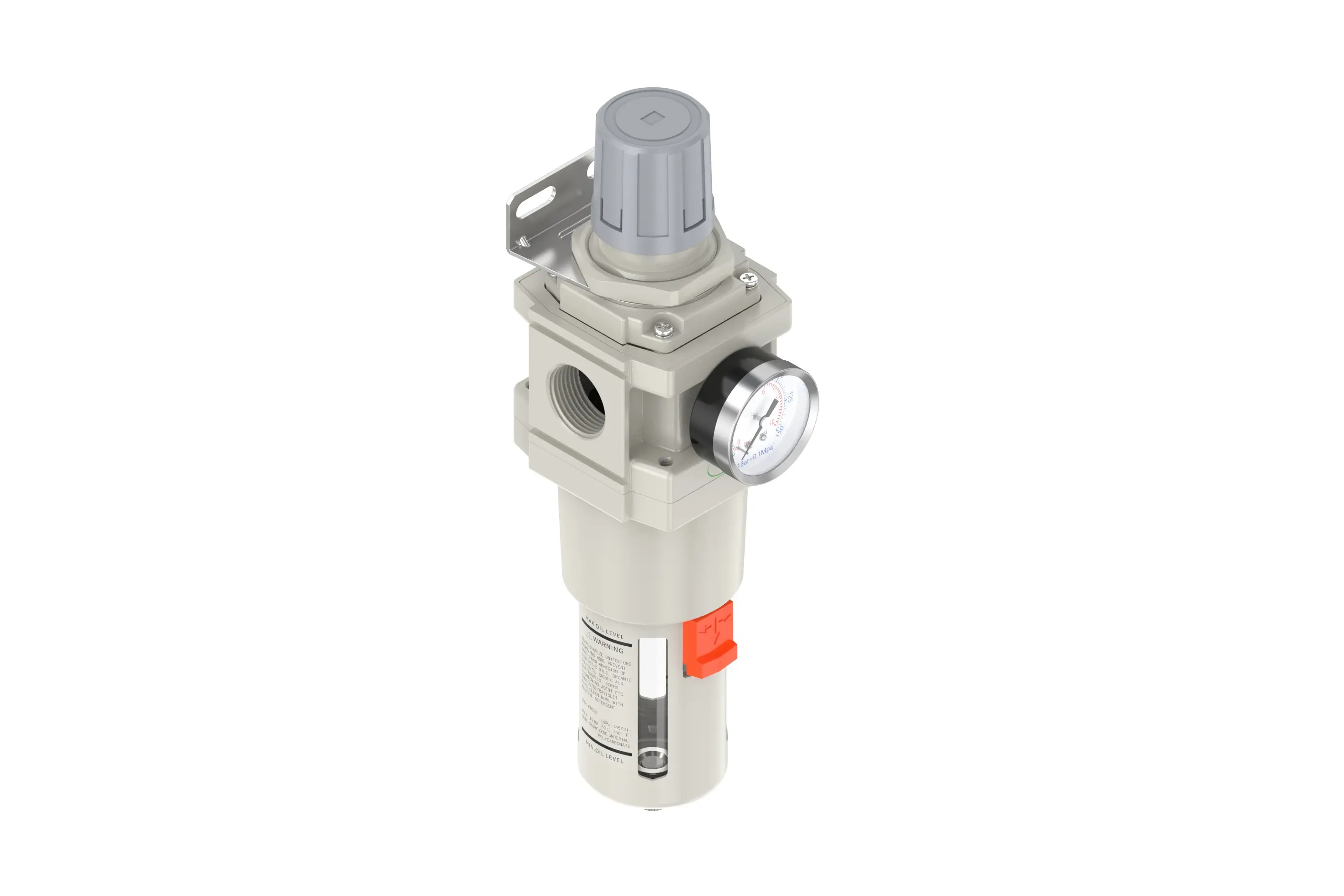
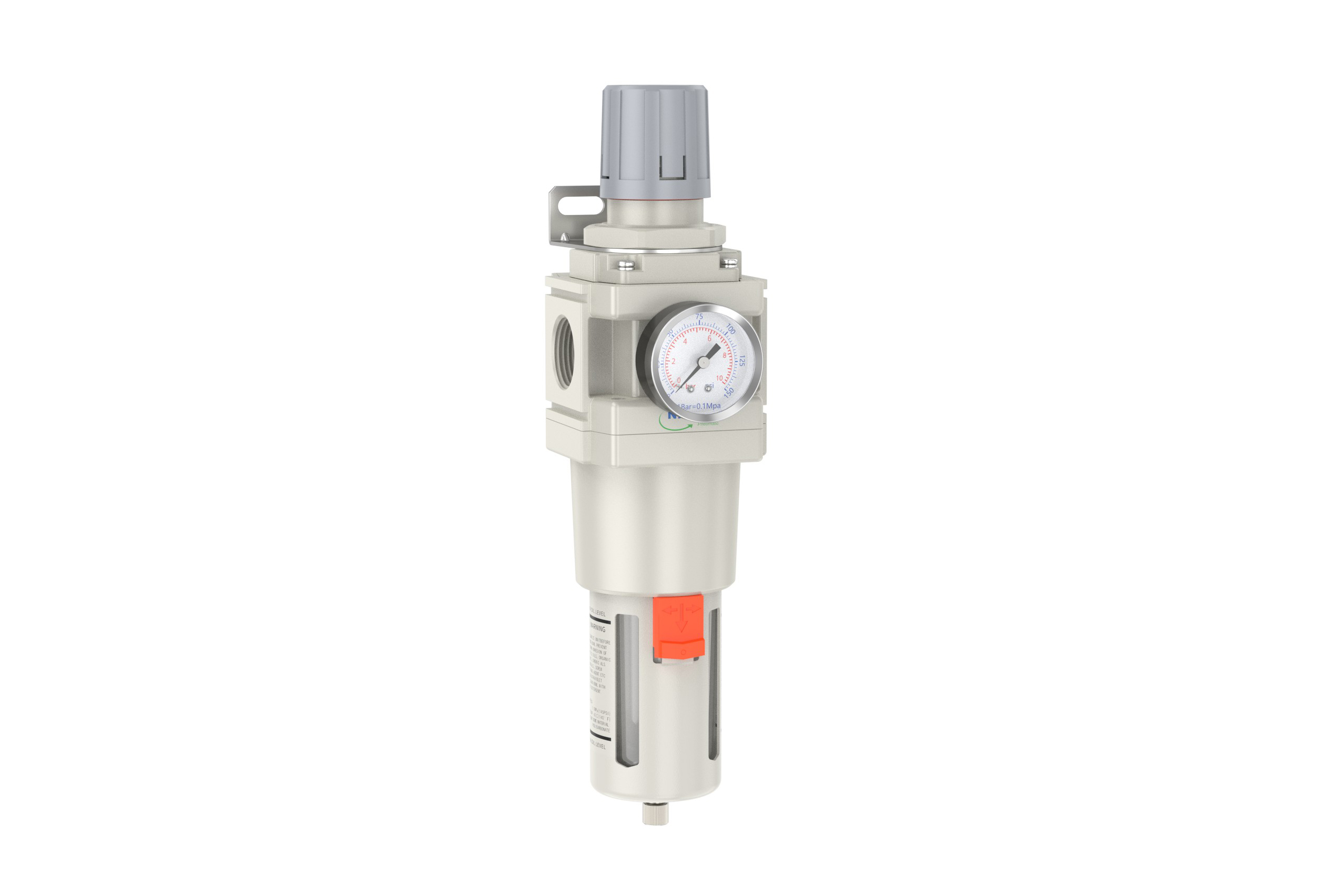
AW5000-06/AW5000-10 AW Filter Regulator
Manual Drain AW5000-06/AW5000-10 Portsize:3/4" 1" AW Filter Regulator
Auto Drain AW5000-06D/AW5000-10D Portsize:3/4" 1" AW Filter Regulator
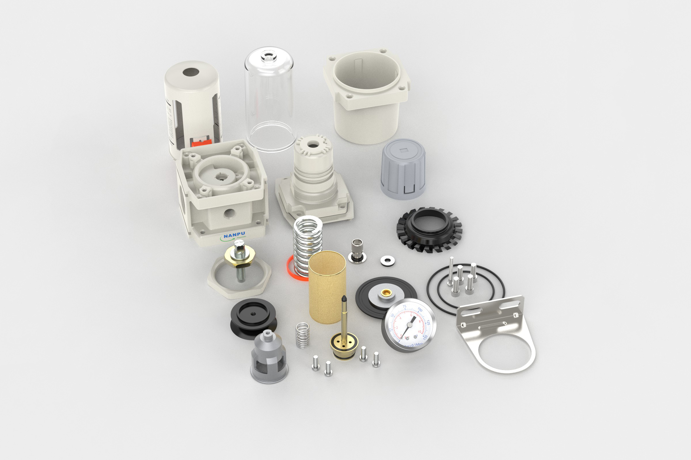
NANPUAW5000-06/AW5000-10 AW Filter Regulator
| AW | 5000 | 10 | BSP | D |
| Series Number | Body Size | Port Size | Thread Type | Drainage Method |
| 2000 | 02:1/4" | BSP | Blank: Differential Pressure Drain | |
| 3000 | 03:3/8" | NPT | A: Manual Drain | |
| 4000 | 04:1/2" | PT | D: Auto Drain | |
| 4000/5000 | 06: 3/4" | |||
| 5000 | 10: 1" |
NANPUTechnical Specifications
| Model | Model | |
| Manual Drain | Auto Drain | (L/min)Rated Flow Rate |
| AW2000-02 | AW2000-02D | 500 |
| AW3000-02 | AW3000-02D | 2000 |
| AW3000-03 | AW3000-03D | 2000 |
| AW4000-04 | AW4000-04D | 4000 |
| AW4000-06 | AW4000-06D | 4500 |
| AW5000-06 | AW5000-06D | 5000 |
| AW5000-10 | AW5000-10D | 5000 |
| Max Input Pressure | 1.2Mpa{12.24kgf/cm²} /174.04Psi |
| Max Operating Pressure | 1.0Mpa{10.2kgf/cm²} /145Psi |
| Temperature Range | 5~60℃ |
| Filtration Accuracy | 0.01μm, 5μm, 40μm |
| Bowl Material | Polycarbonate |
| Bowl Guard | AC2000(None) AC3000~5000(YES) |
| Pressure Range | AC2000~5000/0.05~0.85Mpa (0.51~8.7kgf/cm² )/0~125Psi |
1. Preparation
All calibration assemblies must comply with the maximum flow rate criteria.
Prior to installation, meticulously clean the ports and fittings to effectively prevent dust contamination of the air circuit.
Verify the alignment of the air flow direction with the arrow markings on the product body, and ensure that the port and thread dimensions are properly matched.
2. Pressure Adjustment
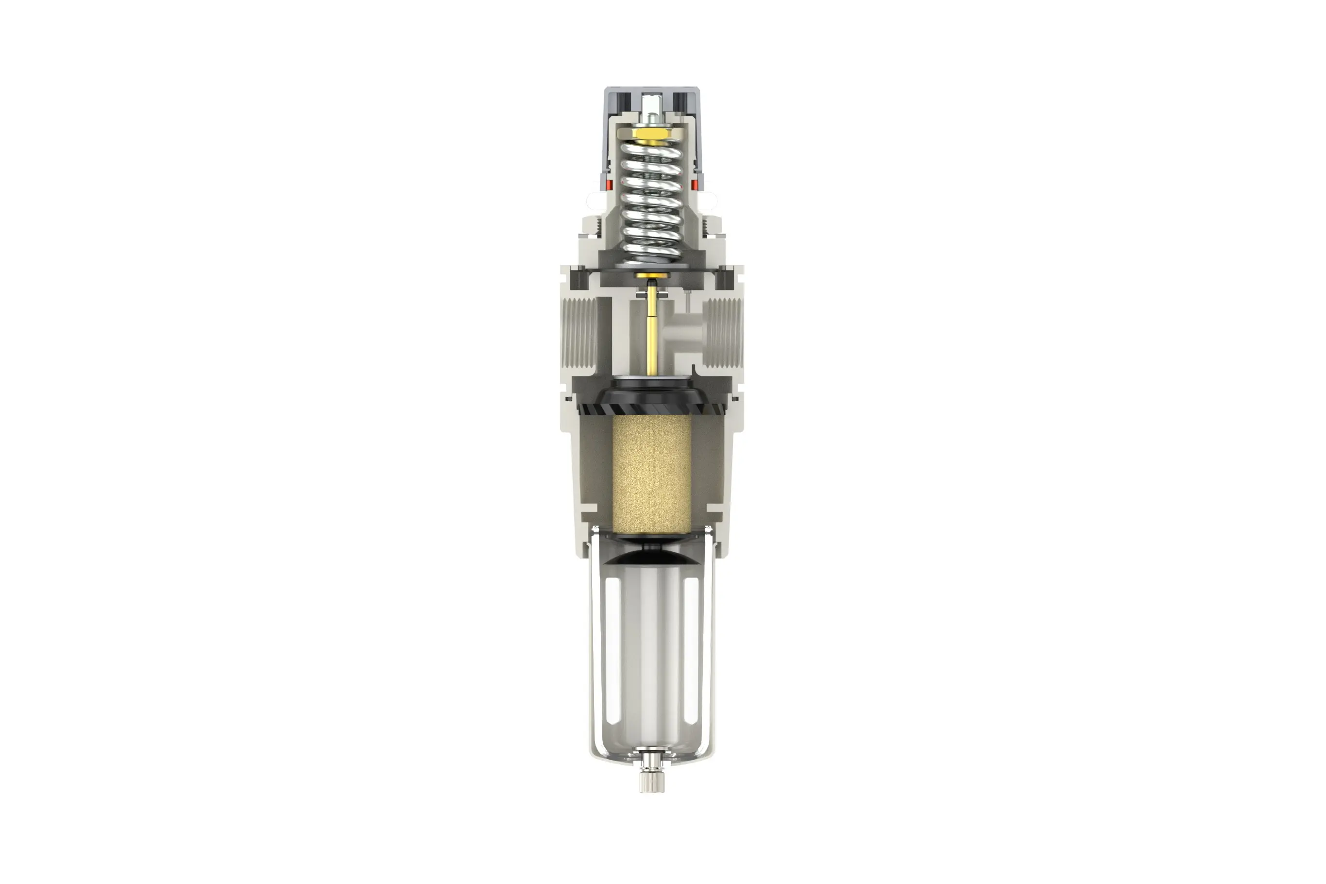
Lift the pressure gauge knob and initiate rotation. A clockwise rotation will induce a gradual and uniform increase in pressure, while a counterclockwise rotation will cause a corresponding decrease. Once the desired pressure value is achieved, cease rotation and securely tighten the knob. Failure to properly lock the knob may result in potential leakage, compromising the system's integrity.
3. Dial Reading
5 - Micron Brass Filter Element: Exhibits exceptional filtration efficiency, extended service life, and reusability.
0.5 and 0.01 - Micron Filter Elements: Capably remove minute impurities.
The drainage column operates on an automatic mechanism. It activates to discharge contents when pressure is absent and seals when air flows through. When the water level surpasses the upper - defined threshold, immediate drainage is mandatory; failure to do so will result in suboptimal dehumidification performance.
4. Drainage
The drainage column is equipped with an automated actuation system. In the absence of pressure, it will initiate the discharge process and seal shut when air is in transit. When the water level reaches or exceeds the pre - set maximum limit, immediate drainage is required; otherwise, it will lead to compromised dehumidification efficiency.
The fitting on the drain head serves as a standardized connection interface for air hoses and can be detached as per specific operational requirements or system configurations.
Utilize an appropriate wrench to torque the fittings to the specified tightness to prevent leakage. During initial installation, an air - release phenomenon may occur. This is not a leakage; rather, it is due to the pressure differential between the internal and external environments, necessitating the expulsion of excess air. In such situations, allow the system to stabilize for a sufficient period, after which it will operate normally.