


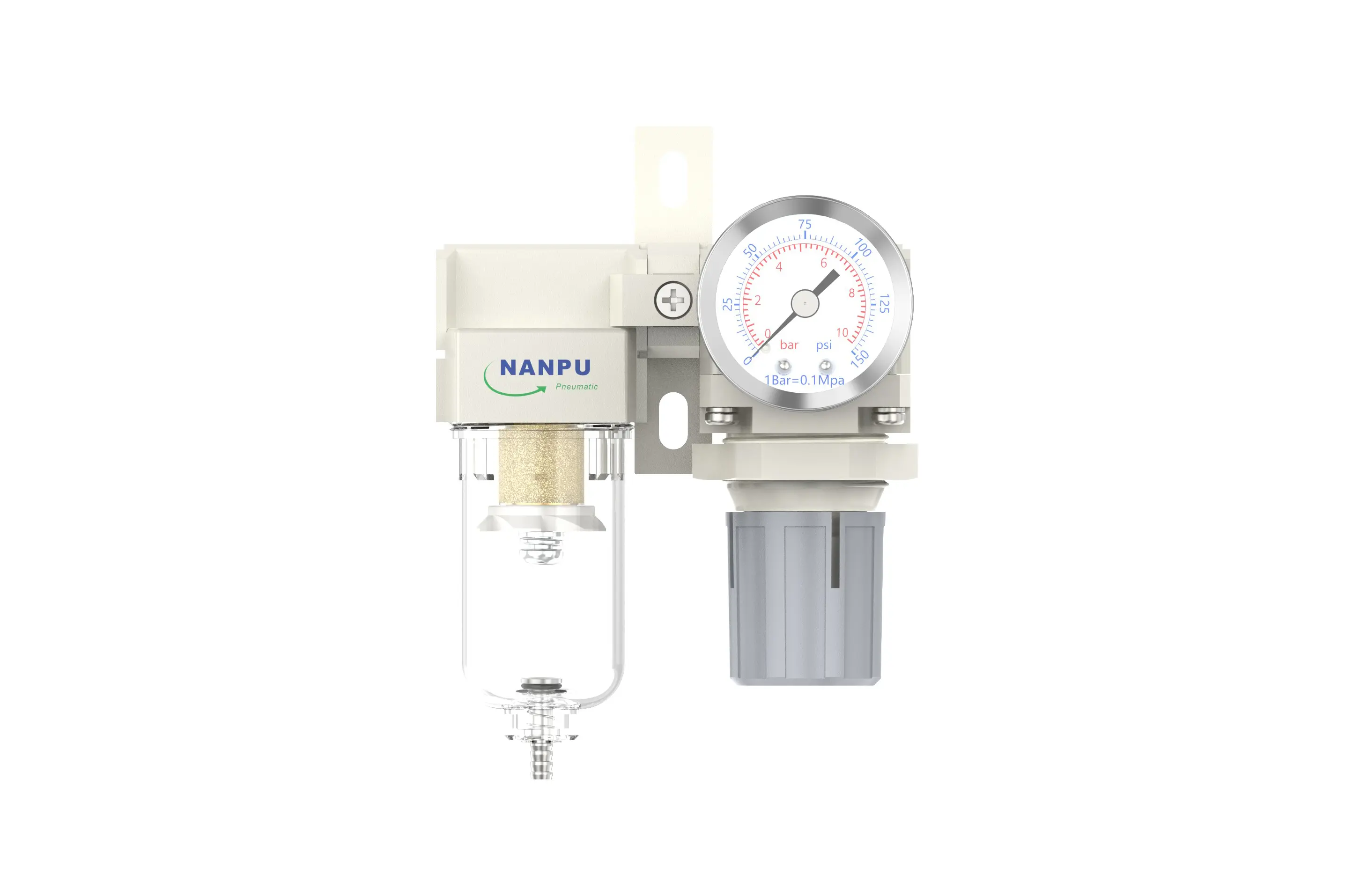
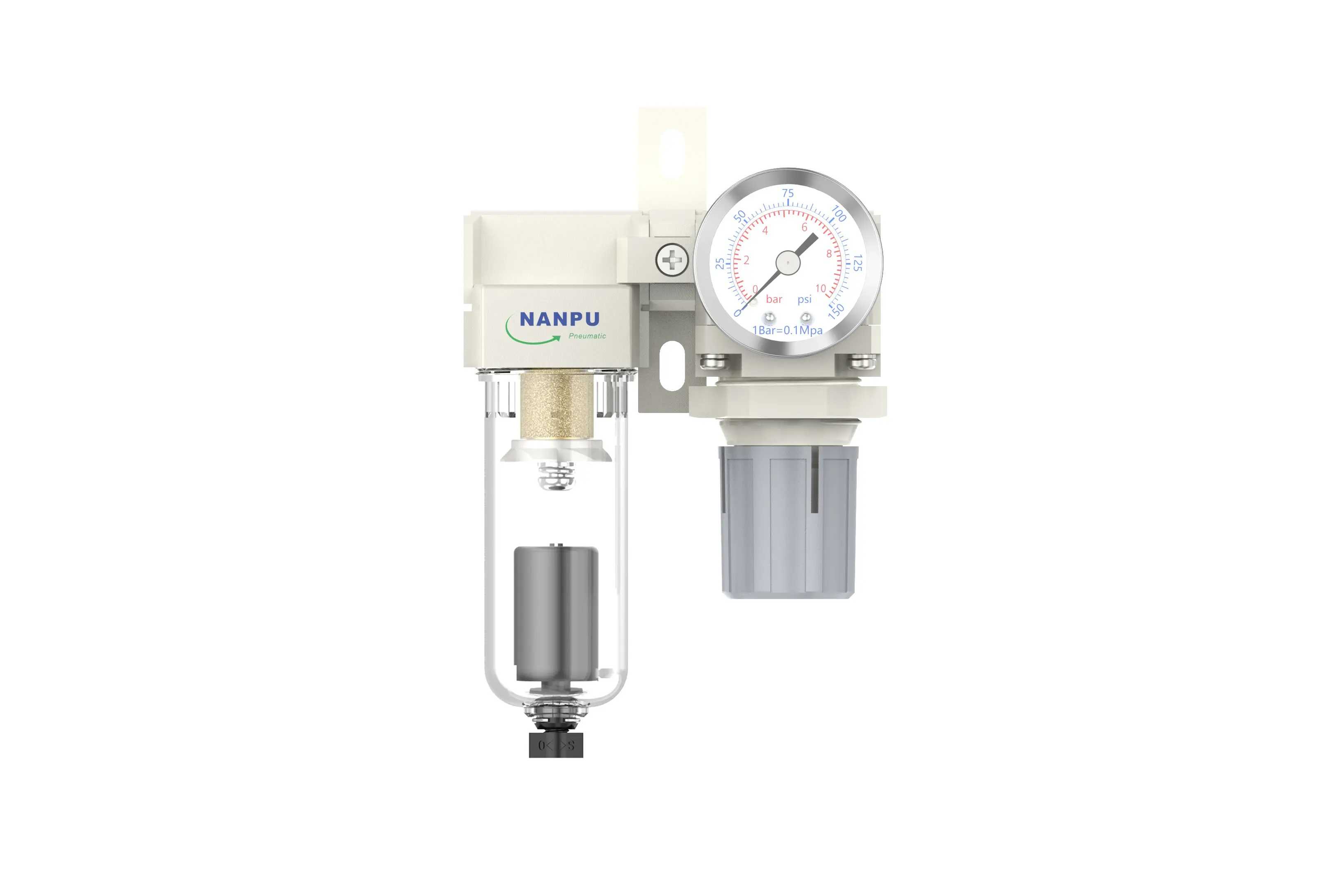
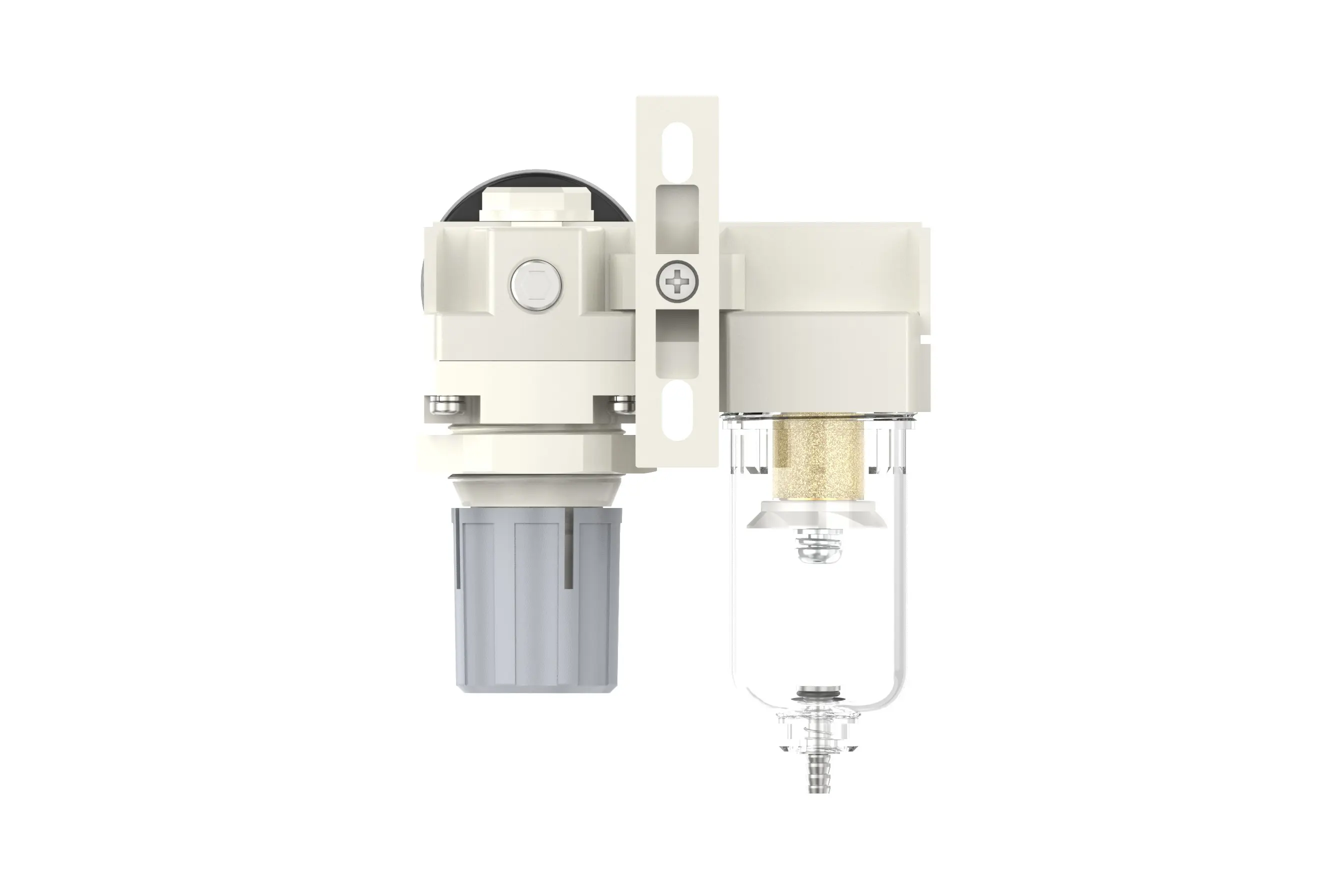
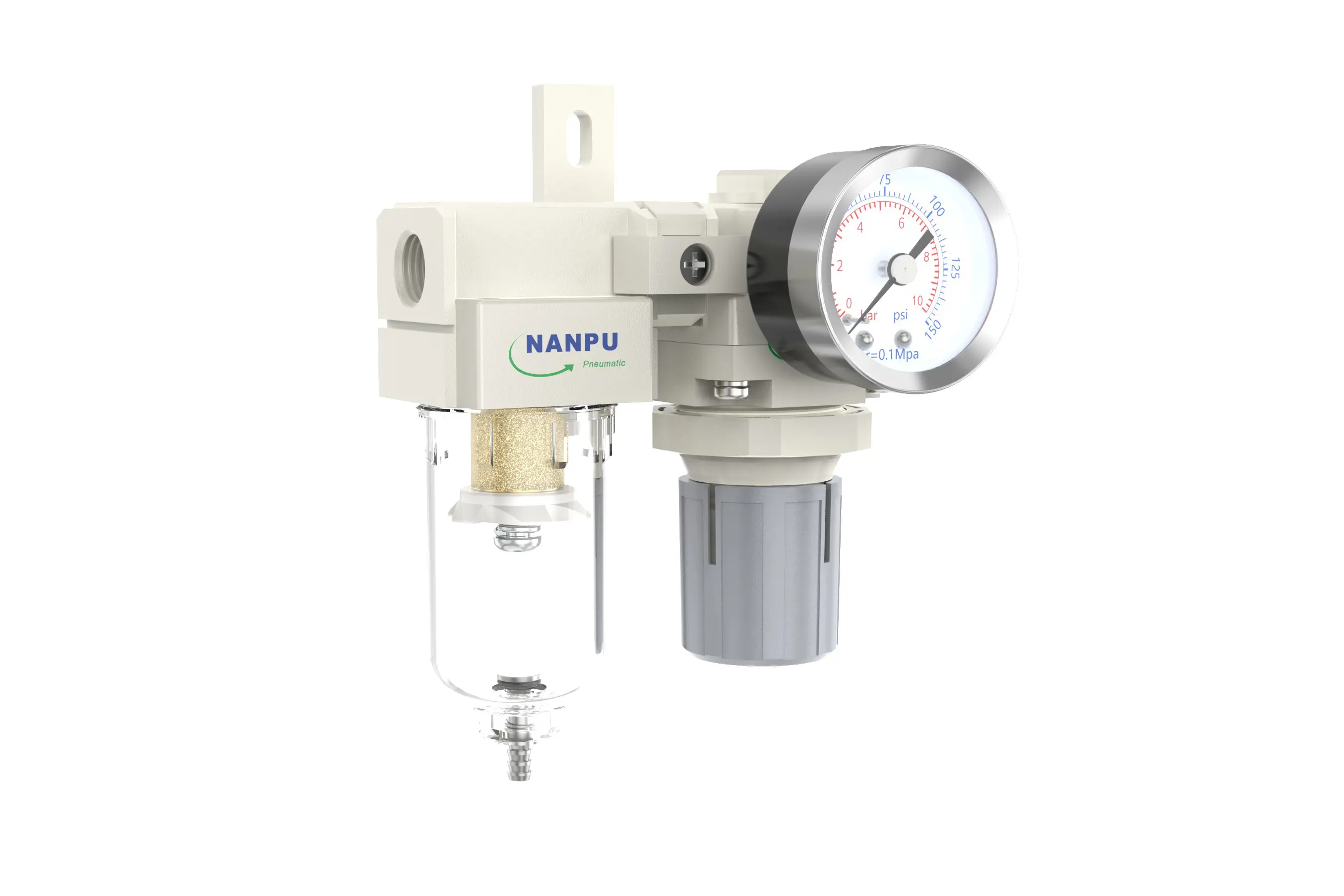

ARF2000-02/ARF2000-02D AW Filter Regulator
description1
ARF2000-02/ARF2000-02D AW Filter Regulator
Manual Drain ARF2000-02 Portsize:1/4" AW Filter Regulator
Auto Drain ARF2000-02D Portsize:1/4" AW Filter Regulator
NANPUARF2000-02/ARF2000-02D ARF Filter Regulator
| ARF | 2000 | 02 | BSP | D |
| Series Number | Body Size | Port Size | Thread Type | Drainage Method |
| 2000 | 02:1/4" | BSP | Blank: Differential Pressure Drain | |
| 3000 | 03:3/8" | NPT | A: Manual Drain | |
| 4000 | 04:1/2" | PT | D: Auto Drain | |
| 4000/5000 | 06: 3/4" | |||
| 5000 | 10: 1" |
NANPUTechnical Specifications
| Model | Model | |
| Manual Drain | Auto Drain | (L/min)Rated Flow Rate |
| ARF2000-02 | ARF2000-02D | 500 |
| ARF3000-02 | ARF3000-02D | 2000 |
| ARF3000-03 | ARF3000-03D | 2000 |
| ARF4000-04 | ARF4000-04D | 4000 |
| ARF4000-06 | ARF4000-06D | 4500 |
| ARF5000-06 | ARF5000-06D | 5000 |
| ARF5000-10 | ARF5000-10D | 5000 |
| Max Input Pressure | 1.2Mpa{12.24kgf/cm²} /174.04Psi |
| Max Operating Pressure | 1.0Mpa{10.2kgf/cm²} /145Psi |
| Temperature Range | 5~60℃ |
| Filtration Accuracy | 0.01μm, 5μm, 40μm |
| Bowl Material | Polycarbonate |
| Bowl Guard | AC2000(None) AC3000~5000(YES) |
| Pressure Range | AC2000~5000/0.05~0.85Mpa (0.51~8.7kgf/cm² )/0~125Psi |
1. Preparation
Every calibration component must comply with the maximum flow rate specification.
Prior to installation, thoroughly clean the ports and fittings to prevent particles from infiltrating the air channel.
Verify that the air flow direction corresponds with the arrow markings on the product body, and ensure that the port and thread dimensions are properly matched.
2. Pressure Adjustment
Lift the pressure gauge knob and commence rotation. A clockwise rotation will lead to a steady increase in pressure, while a counterclockwise rotation will result in a decrease. Once the desired pressure value is achieved, halt rotation and firmly tighten the knob. Failure to properly secure the knob may trigger potential leakage issues.
3. Dial Reading
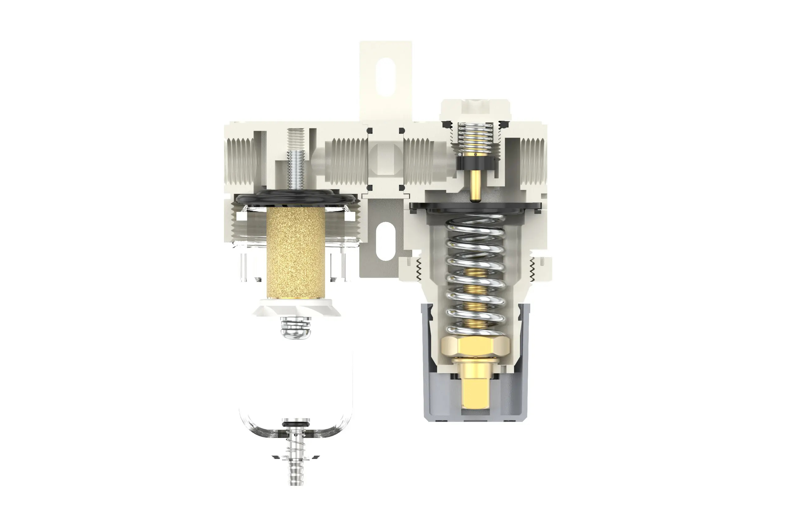
5-Micron Brass Filter Component: Shows superior filtering capability, increased resilience, and is designed for repeated usage.
0.5 and 0.01-Micron Filter Components: Efficiently remove minute impurities from the liquid stream.
The drainage column operates autonomously. It initiates discharge when pressure is absent and seals shut when air circulates. When the water level exceeds the specified maximum, immediate draining is essential; failing to do so will cause a decline in dehumidification effectiveness.
4. Drainage
The drainage column features an automatic control mechanism. It opens to expel substances when there is no pressure and closes as air flows through. When the water level surpasses the set upper limit, urgent draining is necessary; otherwise, dehumidification performance will be significantly impaired.
The fitting on the drainage assembly acts as a connection point for air hoses and can be detached based on specific operating requirements.
Utilize an appropriate spanner to tighten all joints securely to prevent any leakage. During the initial installation, air may be released. This is not a leakage; rather, it is caused by the pressure difference between the internal and external surroundings, necessitating the discharge of excess air. In such situations, allow the system sufficient time to balance, and it will then operate properly.