


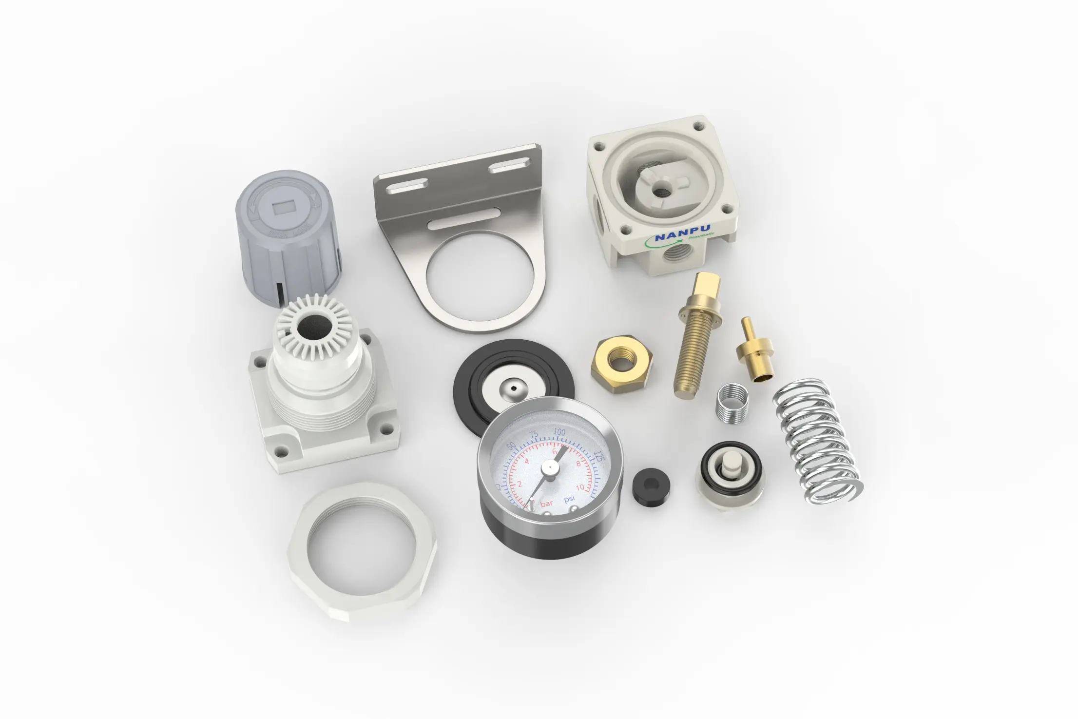
AR2000-02 1/4" AR Air Regulator
description1
AR2000-02 1/4" AR Air Regulator
AR2000-02 1/4" AR Air Regulator
NANPUAR2000-02 1/4" AR Air Regulator
| AR | 2000 | 02 | BSP |
| Series Number | Body Size | Port Size | Thread Type |
| 2000 | 02:1/4" | BSP | |
| 3000 | 03:3/8" | NPT | |
| 4000 | 04:1/2" | PT | |
| 4000/5000 | 06: 3/4" | ||
| 5000 | 10: 1" |
NANPUTechnical Specifications
| Model | Specification |
| AR2000-02 | 500 |
| AR3000-02 | 2000 |
| AR3000-03 | 2000 |
| AR4000-04 | 4000 |
| AR4000-06 | 4500 |
| AR5000-06 | 5000 |
| AR5000-10 | 5000 |
| Max Input Pressure | 1.2Mpa{12.24kgf/cm²} /174.04Psi |
| Max Operating Pressure | 1.0Mpa{10.2kgf/cm²} /145Psi |
| Temperature Range | 5~60℃ |
| Pressure Range | AC2000~5000/0.05~0.85Mpa(0.51~8.7kgf/cm² )/0~125Psi |
All calibration assemblies must strictly conform to the maximum flow rate requirements specified in the technical documentation. This compliance is crucial for ensuring the optimal performance and reliability of the system.
Prior to installation, it is imperative to meticulously clean all ports and fittings using appropriate cleaning agents and procedures. This thorough cleaning process effectively prevents dust, debris, and other contaminants from entering the air pathway, thereby safeguarding the integrity and efficiency of the compressed air system.
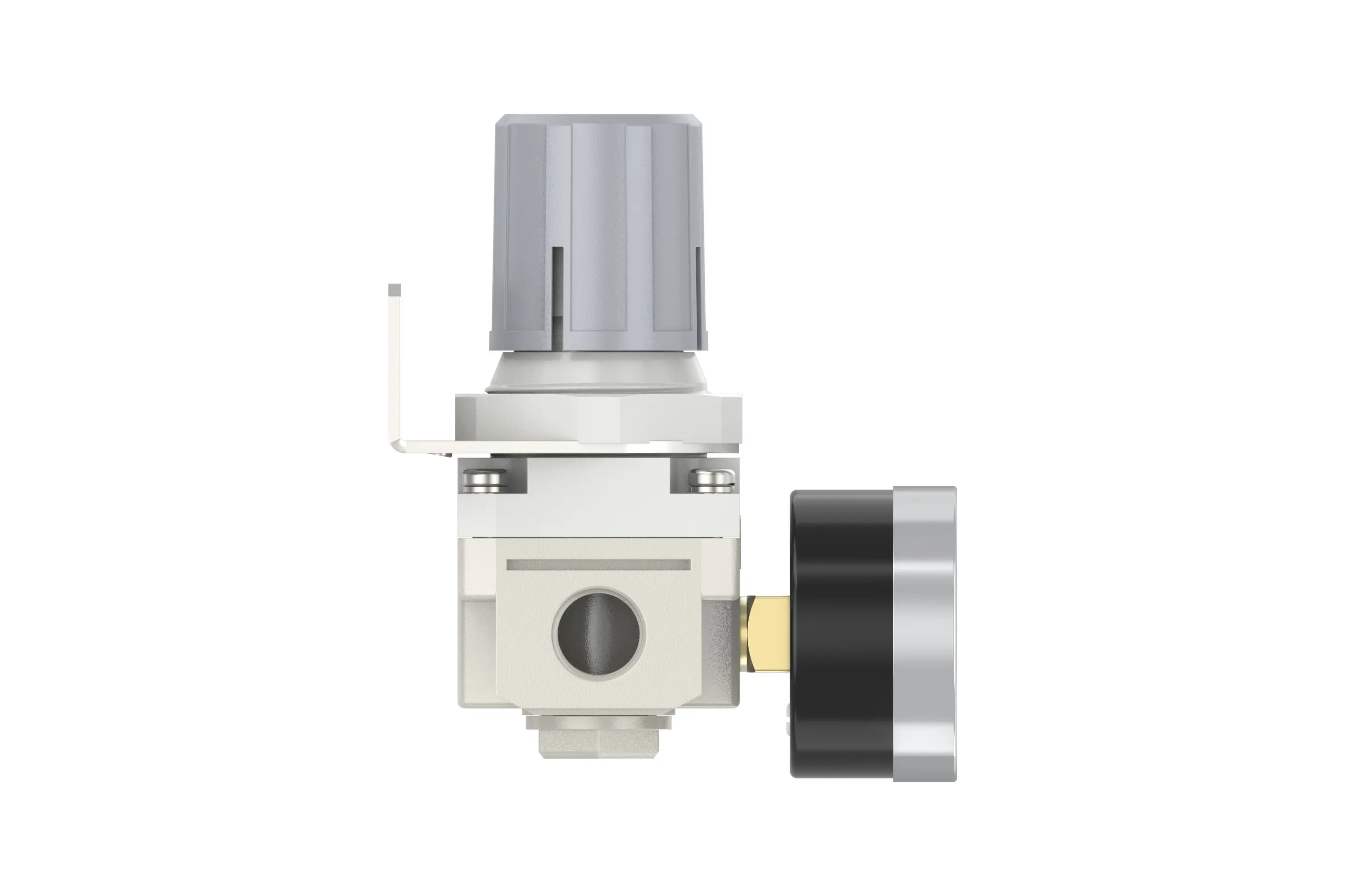
During the installation process, careful attention should be paid to verify that the direction of the air flow aligns precisely with the arrow markings on the product body. Additionally, it is essential to ensure that the port and thread sizes are accurately matched to the corresponding components. This meticulous verification of dimensions and flow direction is necessary to avoid potential installation errors that could lead to system malfunctions or inefficiencies.
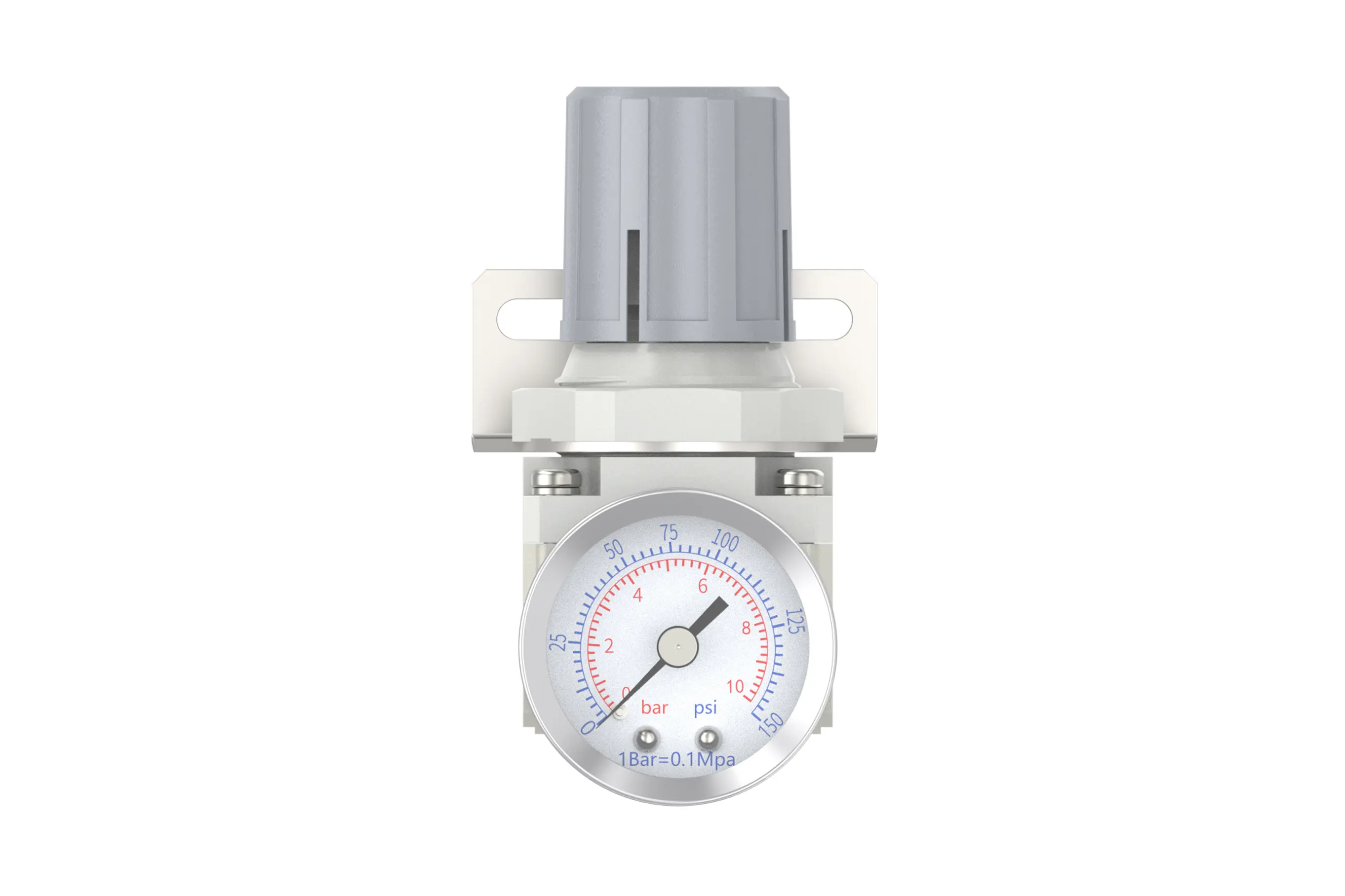
To adjust the pressure, first, lift the knob of the pressure gauge to the unlocked position. Subsequently, rotate the knob to modify the pressure settings. A clockwise rotation will result in a gradual and consistent increase in pressure, while a counterclockwise rotation will cause the pressure to decrease steadily.
It is crucial to monitor the pressure gauge closely and cease rotation once the desired pressure index is achieved. After reaching the required pressure level, firmly lock down the knob to secure the setting. Failing to properly lock the knob may lead to a compromised seal, potentially causing leakage issues that could undermine the system's performance and safety. Regularly check the locked knob during operation to ensure the pressure remains stable and within the specified range.
Ensure that the pressure gauge is securely and properly mounted on the main body using appropriate installation tools and techniques, adhering to the specified torque requirements to prevent any potential leakage or displacement. During the pressure adjustment process, closely monitor the pressure gauge to verify that the readings increase and decrease in a smooth, consistent manner without any erratic fluctuations or sticking. Any abnormal behavior in the gauge readings may indicate issues such as internal obstructions, damaged components, or improper calibration, which should be promptly investigated and addressed to maintain the accuracy and reliability of the pressure monitoring system.