


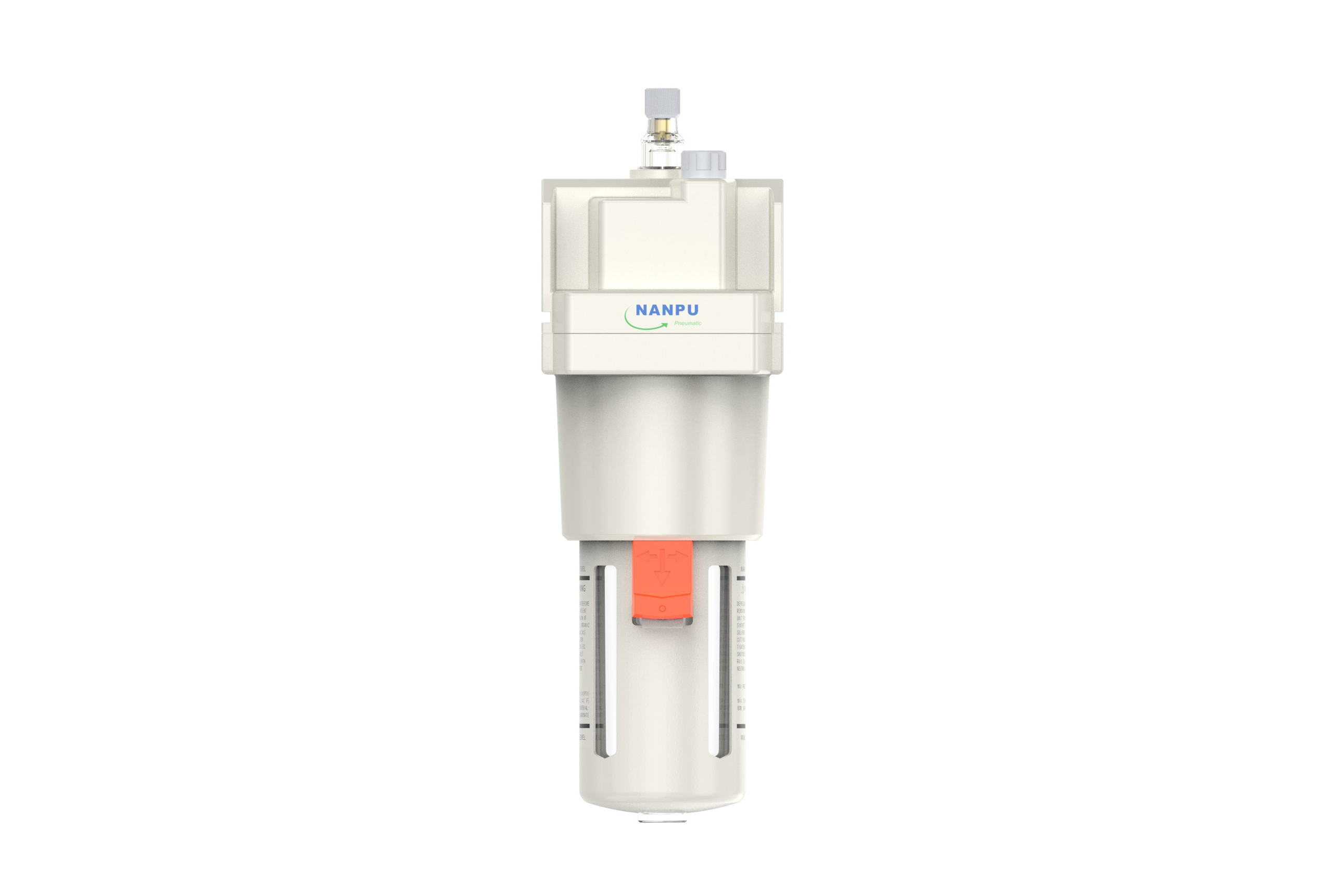
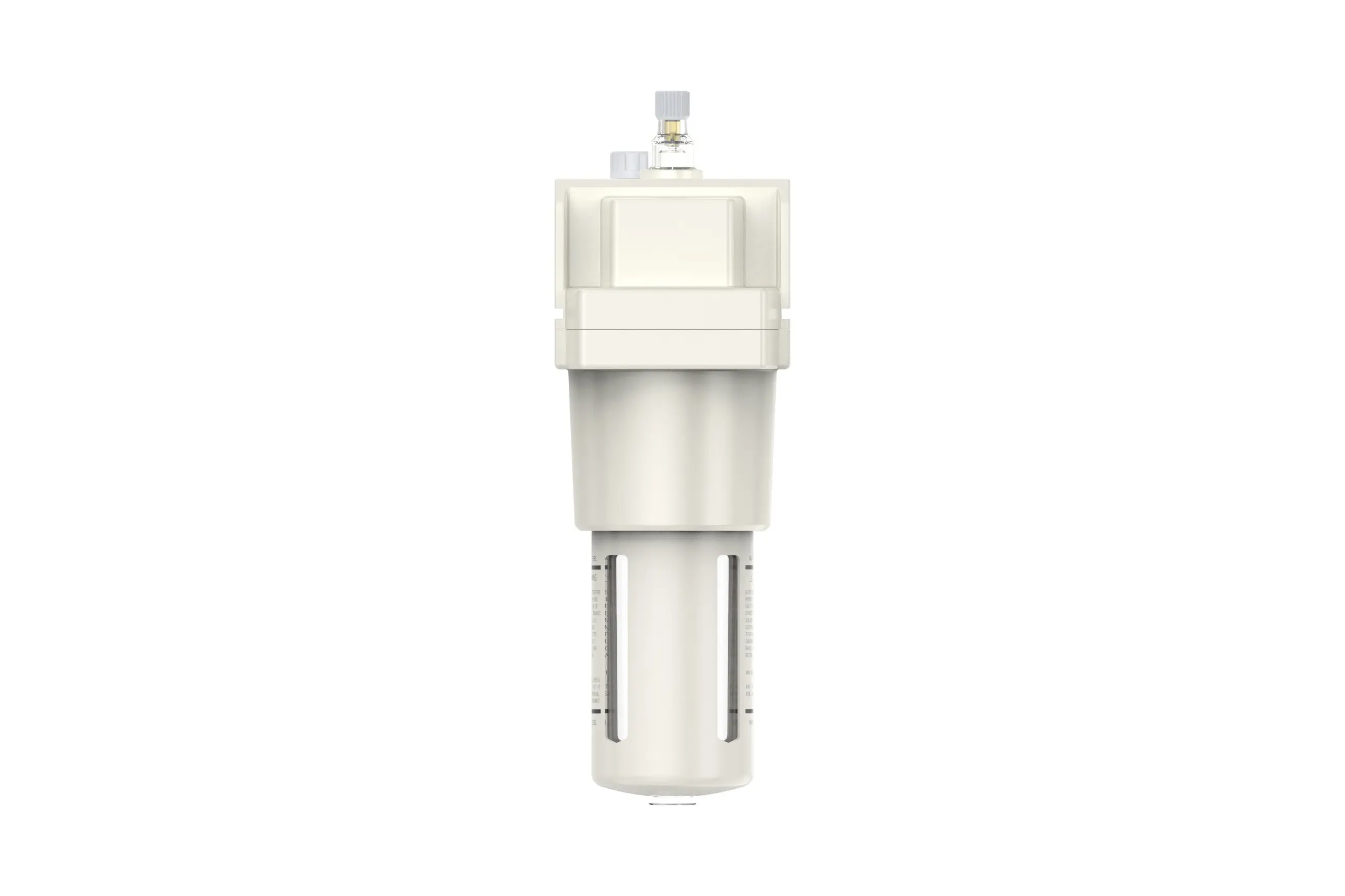
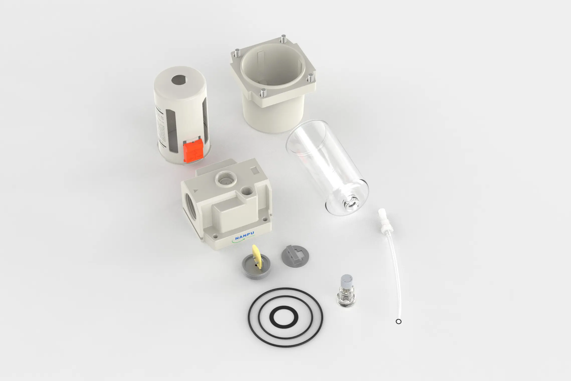
AL5000-06 3/4" AL5000-10 1" AR Air Lubricator
description1
AL5000-06/AL5000-10 3/4" 1" AR Air Lubricator
AL5000-06/AL5000-10 3/4" 1" AR Air Lubricator
NANPUAL5000-06/AL5000-10 3/4" 1" AR Air Lubricator
| AL | 5000 | 10 | BSP |
| Series Number | Body Size | Port Size | Thread Type |
| 2000 | 02:1/4" | BSP | |
| 3000 | 03:3/8" | NPT | |
| 4000 | 04:1/2" | PT | |
| 4000/5000 | 06: 3/4" | ||
| 5000 | 10: 1" |
NANPUTechnical Specifications
| Model | Specification |
| AL2000-02 | 500 |
| AL3000-02 | 2000 |
| AL3000-03 | 2000 |
| AL4000-04 | 4000 |
| AL4000-06 | 4500 |
| AL5000-06 | 5000 |
| AL5000-10 | 5000 |
| Max Input Pressure | 1.2Mpa{12.24kgf/cm²} /174.04Psi |
| Max Operating Pressure | 1.0Mpa{10.2kgf/cm²} /145Psi |
| Temperature Range | 5~60℃ |
| Pressure Range | AC2000~5000/0.05~0.85Mpa (0.51~8.7kgf/cm² )/0~125Psi |
| Bowl Material | Polycarbonate |
| Suggested Oil | Turbine Oil No. 1 ISO-VG32 |
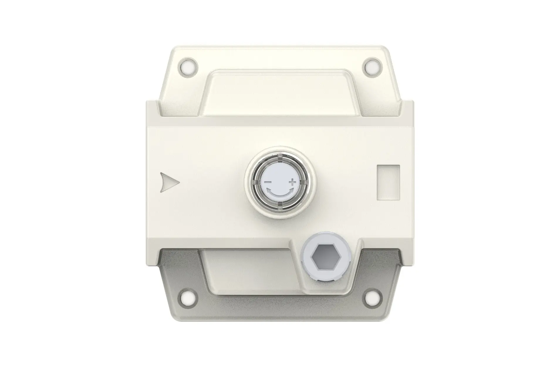
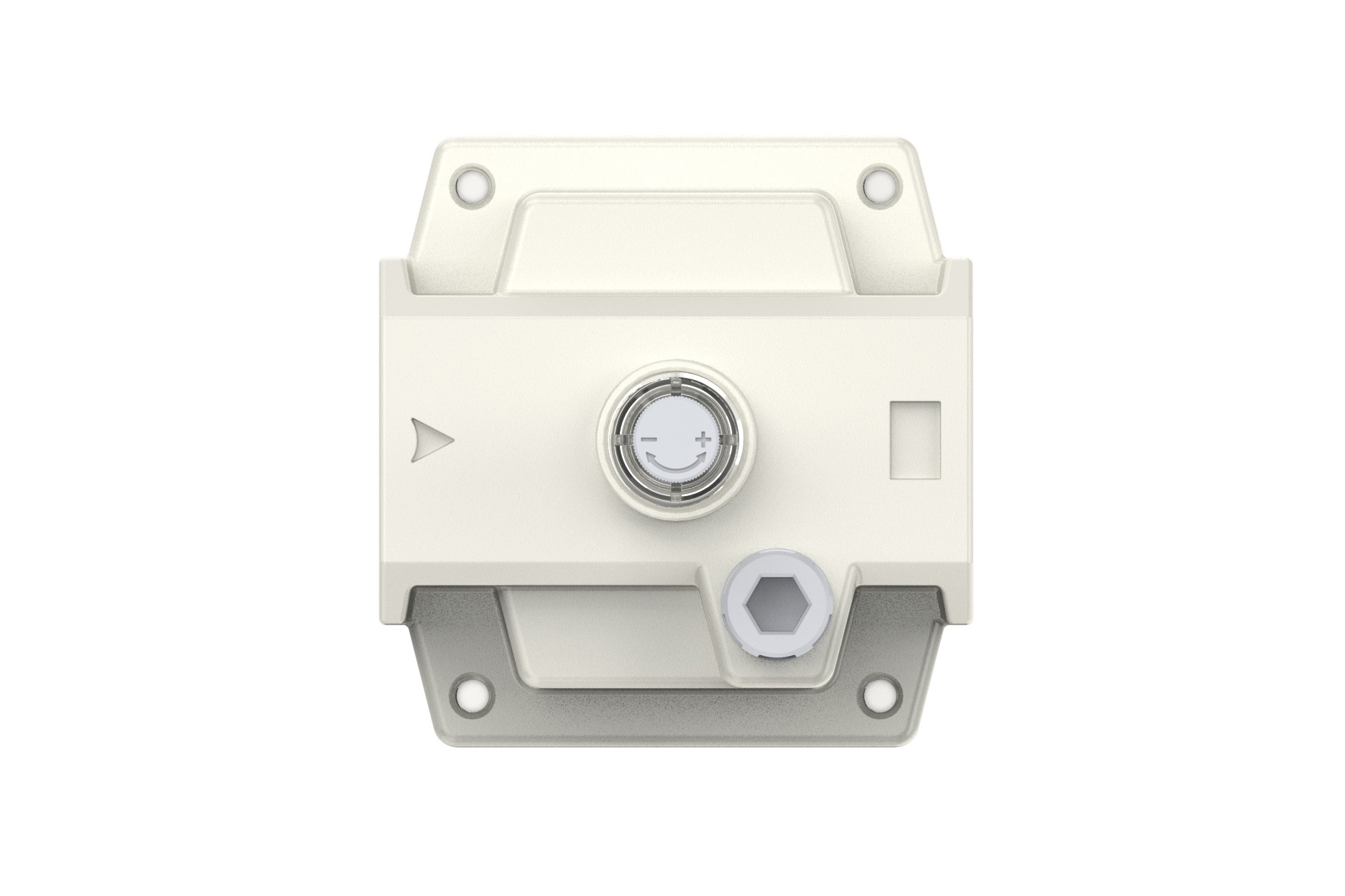
All calibration assemblies must be meticulously fabricated and assembled to fully comply with the specified maximum flow requirements. This compliance is crucial for ensuring the optimal performance, reliability, and efficiency of the entire system. Prior to installation, it is imperative to conduct a comprehensive cleaning of all ports and fittings using appropriate industrial - grade solvents and tools. This thorough cleaning process effectively prevents dust, debris, and other contaminants from entering the air path, thereby safeguarding against potential blockages and system failures. During installation, scrupulously verify the alignment of the air flow direction with the arrow markings on the product body. Additionally, carefully check that the port and thread sizes match precisely to ensure a secure, leak - free connection.
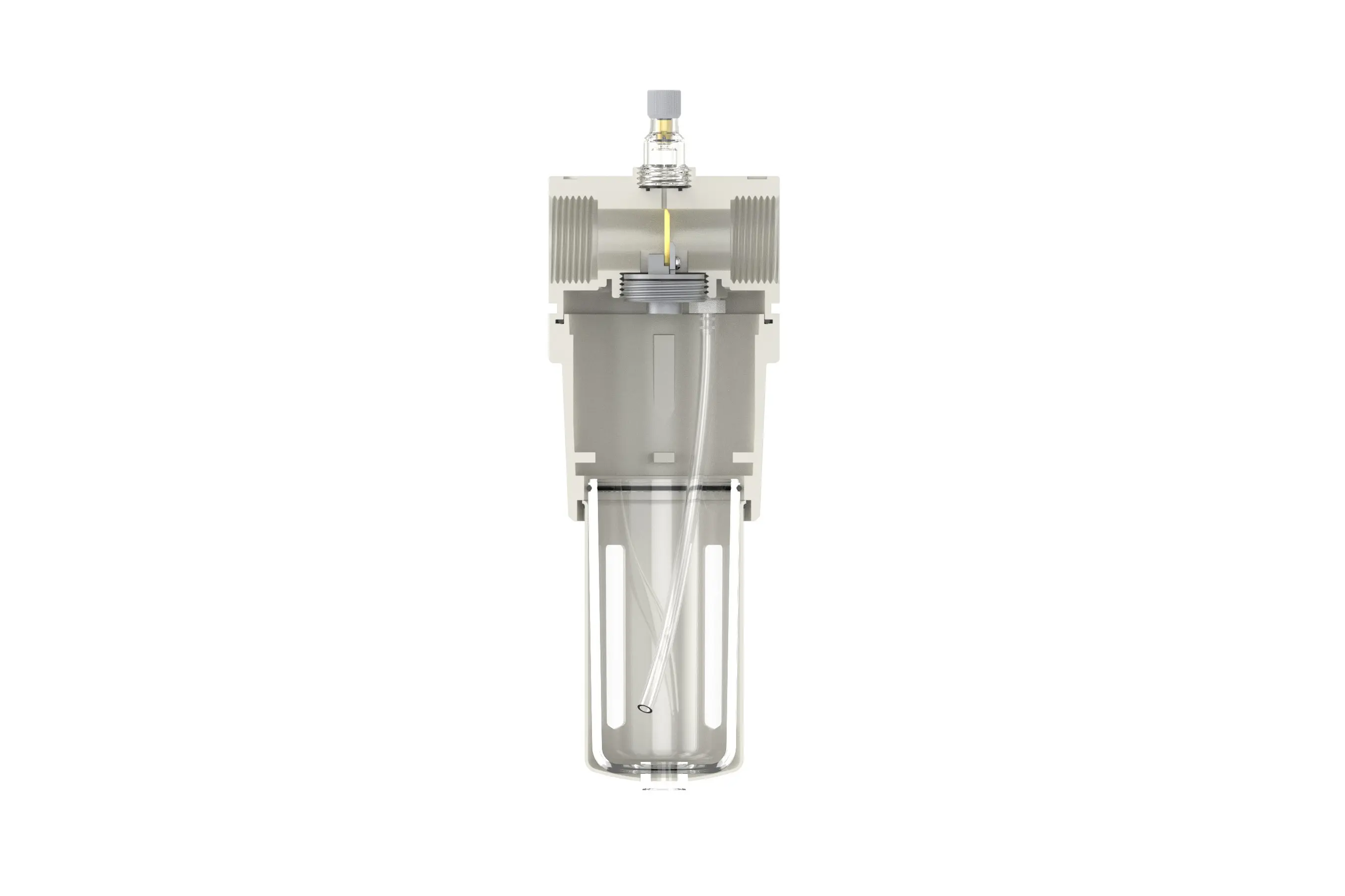
In the operation of the lubrication system, precise adjustment of the oil absorption speed can be achieved by manipulating the needle valve. When rotating the needle valve in the clockwise direction, which corresponds to the “+” symbol marked on the valve, the valve's orifice gradually expands. This expansion allows for a greater volume of oil to be drawn into the system per unit of time, thus increasing the oil absorption speed.
Conversely, when the needle valve is rotated counter - clockwise, following the “ - ” direction, the orifice size of the valve progressively decreases. As a result, the oil absorption rate slows down. Continuing to turn in this direction will eventually cause the oil intake to stop completely, enabling accurate control of the lubrication process according to the system's requirements.
To execute the refueling process accurately, initiate the operation by rotating the refueling screw in a clockwise direction to open the access port for lubricant introduction. It is of critical importance to adhere to the specified filling protocol, ensuring that the volume of oil added does not surpass 80% of the bowl's total capacity. Overfilling may lead to lubricant spillage during system operation, potential contamination of adjacent components, and interference with the proper functioning of the lubrication mechanism. Once the refueling is completed, employ an appropriate torque - controlled tool to securely tighten the refueling screw, thereby restoring the system's hermetic seal and preventing any leakage of lubricant.