


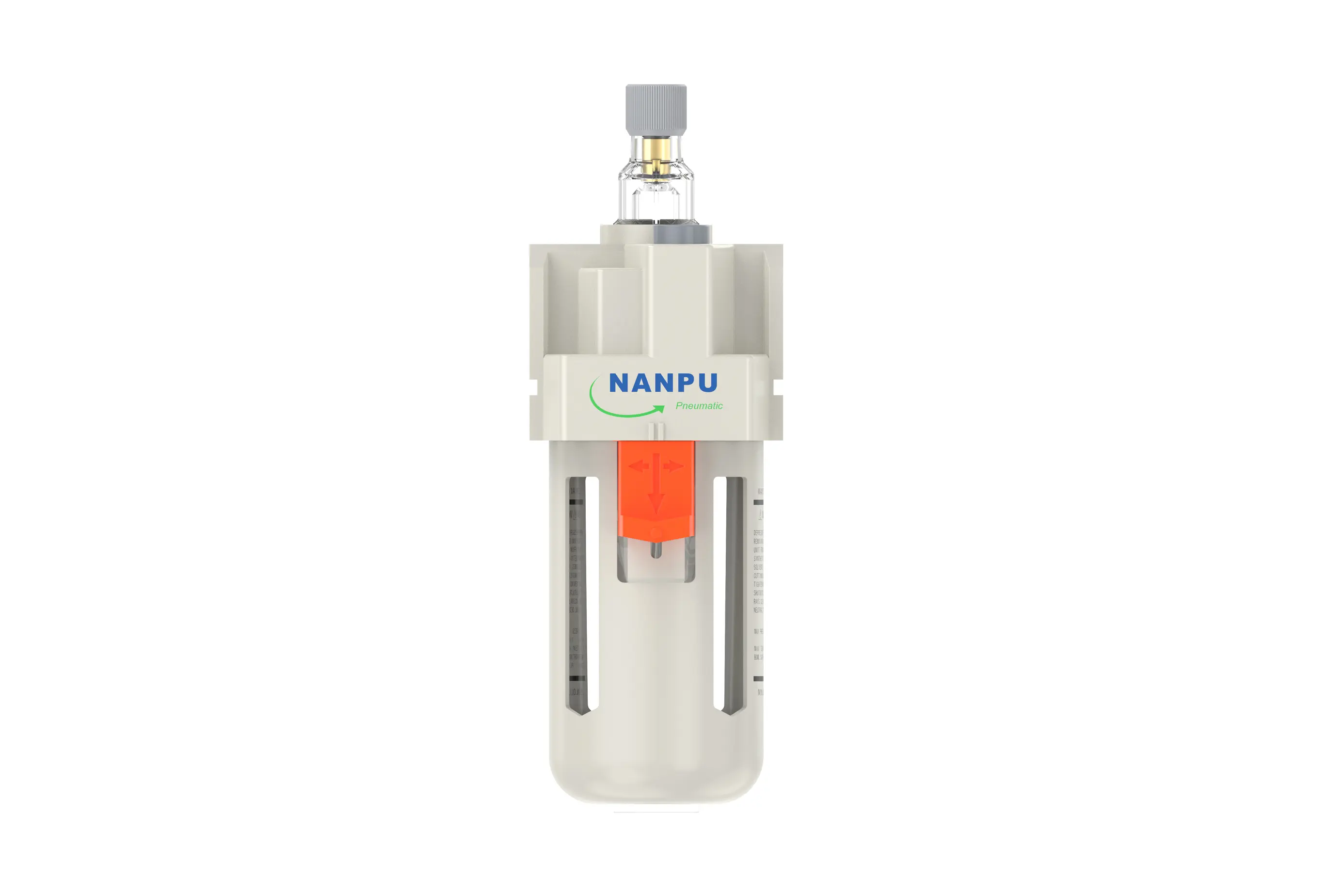
AL3000-03 3/8' AL4000-04 1/2" AL5000-06 3/4" AR Air Lubricator
description1
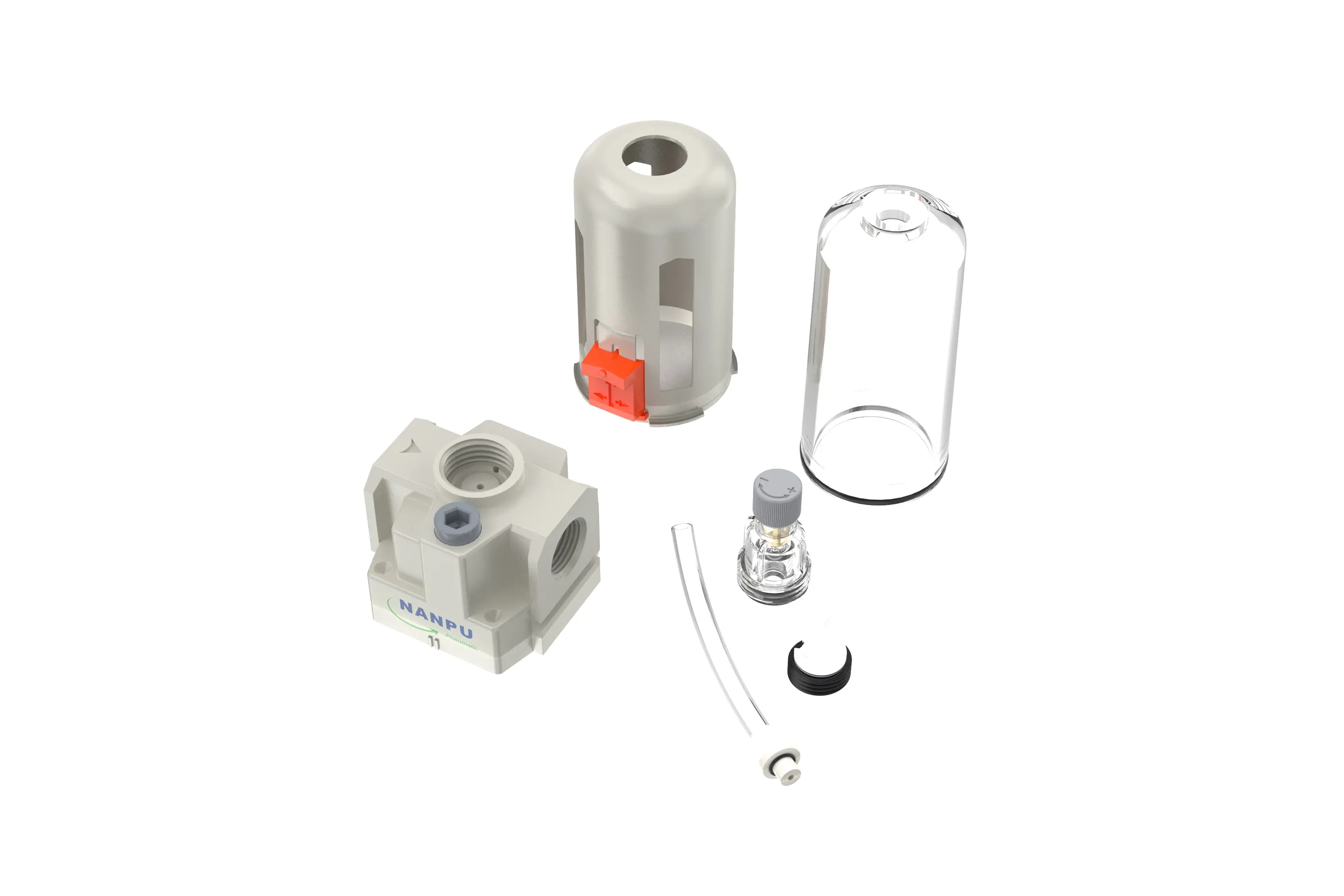
AL3000-03/AL4000-04/AL4000-06 3/8" 1/2" 3/4" AR Air Lubricator
AL3000-03/AL4000-04/AL4000-06 3/8" 1/2" 3/4" AR Air Lubricator
NANPUAL3000-03/AL4000-04/AL4000-06
| AL | 3000 | 03 | BSP |
| Series Number | Body Size | Port Size | Thread Type |
| 2000 | 02:1/4" | BSP | |
| 3000 | 03:3/8" | NPT | |
| 4000 | 04:1/2" | PT | |
| 4000/5000 | 06: 3/4" | ||
| 5000 | 10: 1" |
NANPUTechnical Specifications
| Model | Specification |
| AL2000-02 | 500 |
| AL3000-02 | 2000 |
| AL3000-03 | 2000 |
| AL4000-04 | 4000 |
| AL4000-06 | 4500 |
| AL5000-06 | 5000 |
| AL5000-10 | 5000 |
| Max Input Pressure | 1.2Mpa{12.24kgf/cm²} /174.04Psi |
| Max Operating Pressure | 1.0Mpa{10.2kgf/cm²} /145Psi |
| Temperature Range | 5~60℃ |
| Pressure Range | AC2000~5000/0.05~0.85Mpa (0.51~8.7kgf/cm² )/0~125Psi |
| Bowl Material | Polycarbonate |
| Suggested Oil | Turbine Oil No. 1 ISO-VG32 |
All calibration assemblies must be meticulously engineered and assembled to fully comply with the specified maximum flow rate requirements. Rigorous adherence to these requirements is not only essential for ensuring the system's optimal performance but also for maintaining its long - term reliability and efficiency. Any deviation from the maximum flow criteria can lead to subpar functionality, increased energy consumption, and potential system failures.
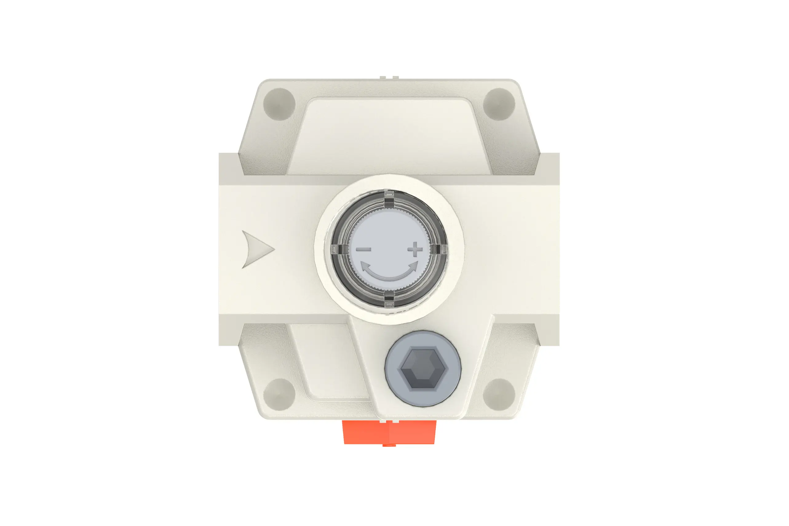
When it comes to adjusting the oil absorption speed of the lubrication system, precisely manipulate the needle valve. Rotating the needle valve in the clockwise direction, as indicated by the “+” symbol, gradually enlarges the valve's orifice. This allows a greater volume of oil to be drawn into the system, thereby increasing the oil absorption speed. This is ideal for high - demand operational scenarios.
Conversely, rotating the needle valve counterclockwise, corresponding to the “-” direction, progressively narrows the orifice. As a result, the oil absorption rate slows down. Continuing to turn in this direction will eventually halt the oil intake, enabling accurate control of the lubrication process.
To perform the refueling procedure correctly, rotate the refueling screw in a clockwise direction to open the access point for adding lubricant. It is essential to adhere to the specified safety and operational guidelines by ensuring that the volume of oil introduced does not surpass 80% of the bowl's total capacity. Overfilling can lead to oil spillage during system operation, potential contamination of the surrounding components, and interference with the proper functioning of the lubrication system. Once the refueling is complete, use an appropriate torque - rated tool to securely tighten the refueling screw, restoring the system's airtight integrity and preventing any leakage of lubricant.