


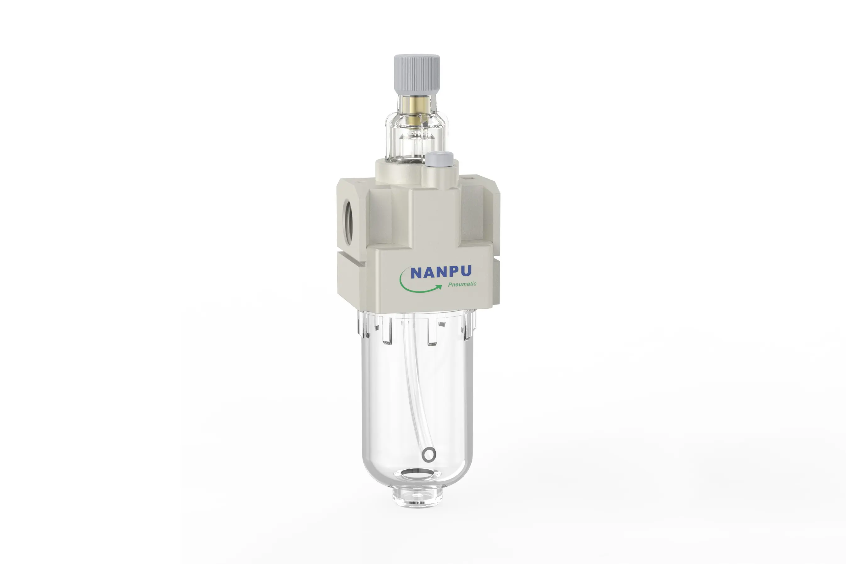
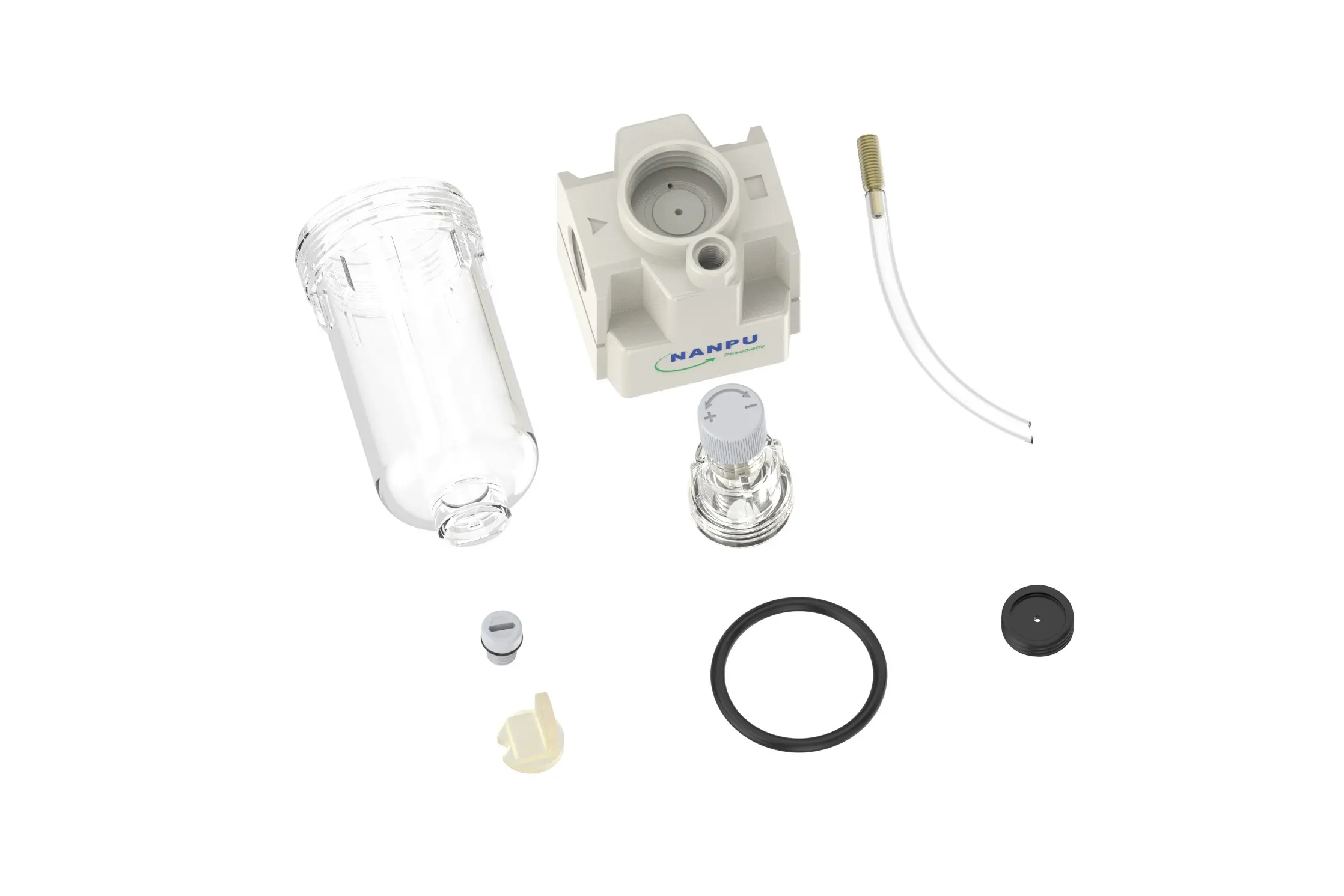
AL2000-02 1/4" AR Air Lubricator
description1
AL2000-02 1/4" AR Air Lubricator
AL2000-02 1/4" AR Air Lubricator
NANPUAL2000-02 1/4" AR Air Lubricator
| AL | 2000 | 02 | BSP |
| Series Number | Body Size | Port Size | Thread Type |
| 2000 | 02:1/4" | BSP | |
| 3000 | 03:3/8" | NPT | |
| 4000 | 04:1/2" | PT | |
| 4000/5000 | 06: 3/4" | ||
| 5000 | 10: 1" |
NANPUTechnical Specifications
| Model | Specification |
| AL2000-02 | 500 |
| AL3000-02 | 2000 |
| AL3000-03 | 2000 |
| AL4000-04 | 4000 |
| AL4000-06 | 4500 |
| AL5000-06 | 5000 |
| AL5000-10 | 5000 |
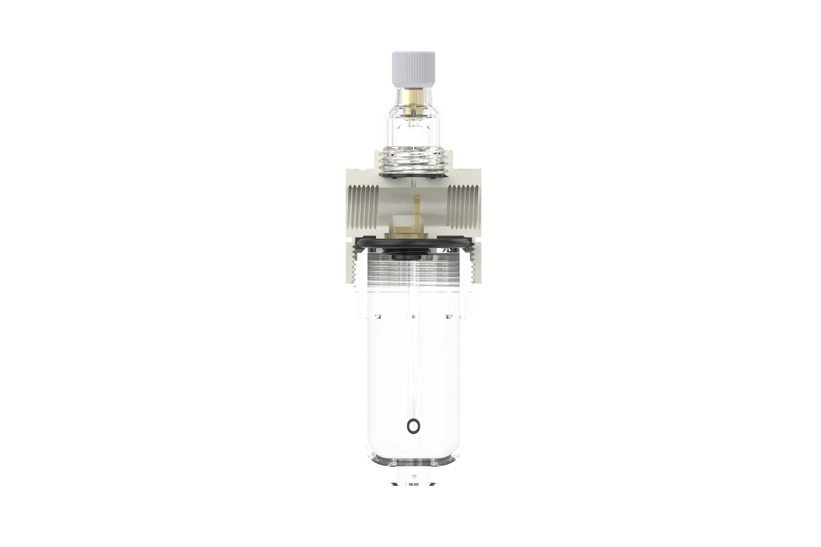
| Max Input Pressure | 1.2Mpa{12.24kgf/cm²} /174.04Psi |
| Max Operating Pressure | 1.0Mpa{10.2kgf/cm²} /145Psi |
| Temperature Range | 5~60℃ |
| Pressure Range | AC2000~5000/0.05~0.85Mpa (0.51~8.7kgf/cm² )/0~125Psi |
| Bowl Material | Polycarbonate |
| Suggested Oil | Turbine Oil No. 1 ISO-VG32 |
All calibration assemblies must be fabricated and assembled in strict accordance with the maximum flow rate requirements stipulated in the technical documentation. This compliance is essential for guaranteeing the optimal performance, efficiency, and reliability of the overall system. Meticulous attention to these specifications during the assembly process ensures that the system operates within the designated parameters, preventing potential inefficiencies or failures that could arise from non - adherence to the maximum flow criteria.
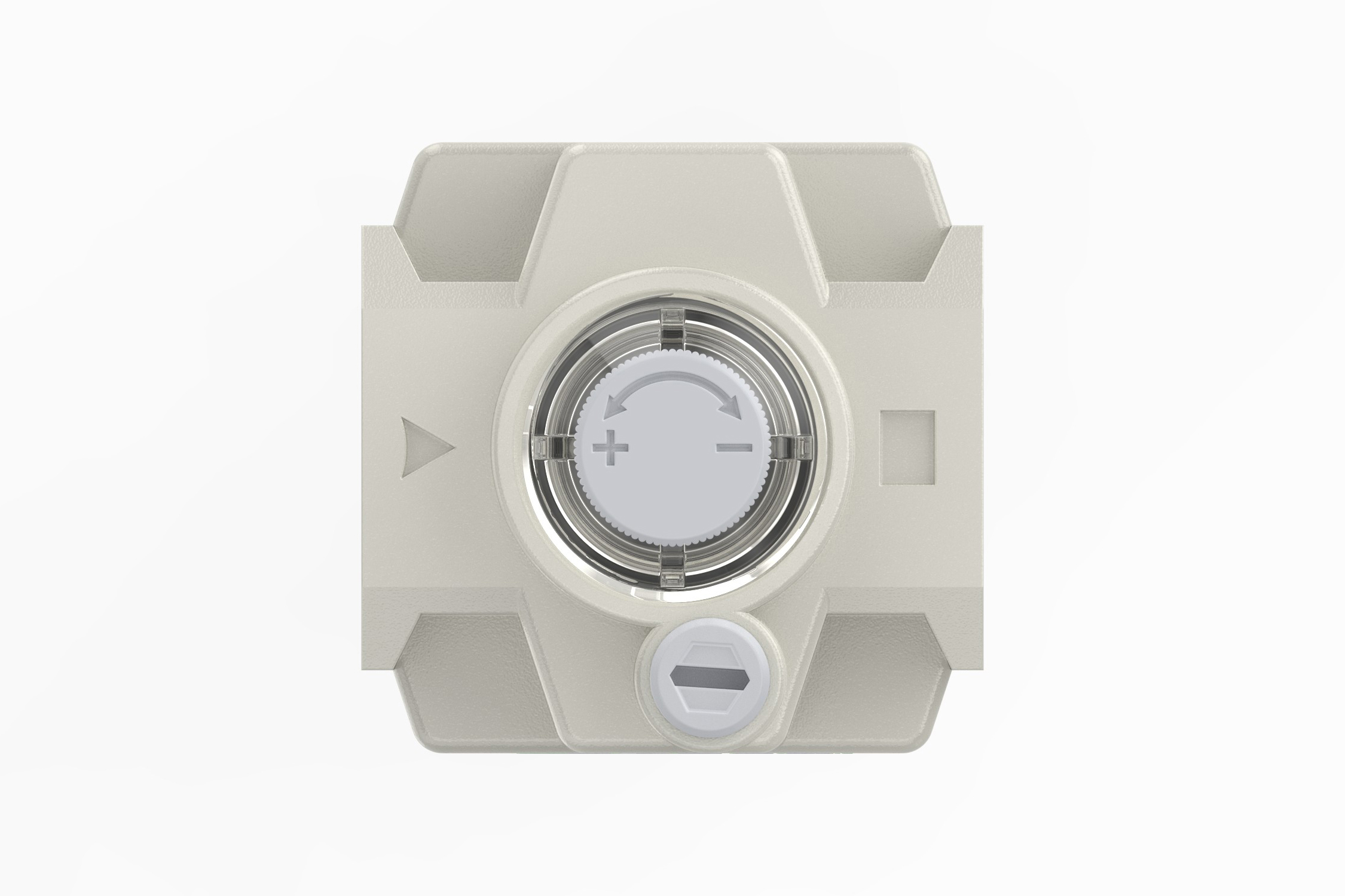
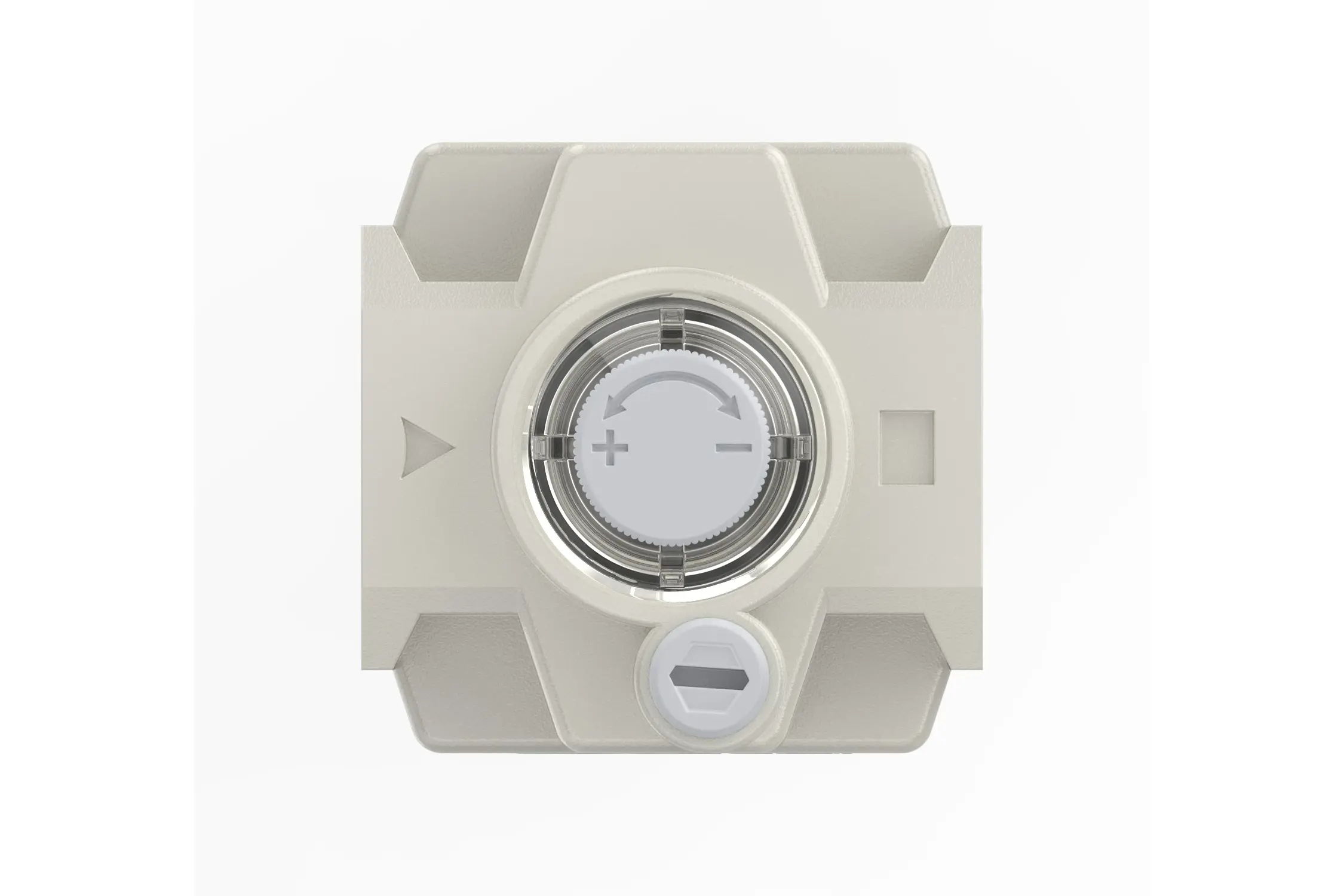
To regulate the oil absorption rate, rotate the needle valve. A clockwise rotation, corresponding to the “+” direction indicated on the valve, will incrementally increase the oil absorption speed. This adjustment facilitates a more rapid intake of oil, which may be necessary for optimizing the lubrication process under specific operating conditions. Conversely, turning the needle valve counterclockwise, or in the “-” direction, will gradually decrease the oil absorption rate. Continued rotation in this direction can ultimately bring the oil absorption process to a halt. This precise control mechanism allows operators to fine - tune the oil flow according to the exact requirements of the system, ensuring efficient operation and preventing over - lubrication or under - lubrication, both of which can lead to equipment wear, inefficiency, or failure.
To commence the refueling procedure, rotate the refueling screw in a clockwise direction to open the access point for adding lubricant. It is imperative to exercise caution and ensure that the volume of oil introduced into the reservoir bowl does not surpass 80% of its total capacity. This critical threshold is established to prevent overfilling, which can lead to oil spillage during system operation, potential contamination of the surrounding environment, and interference with the proper functioning of associated components.