


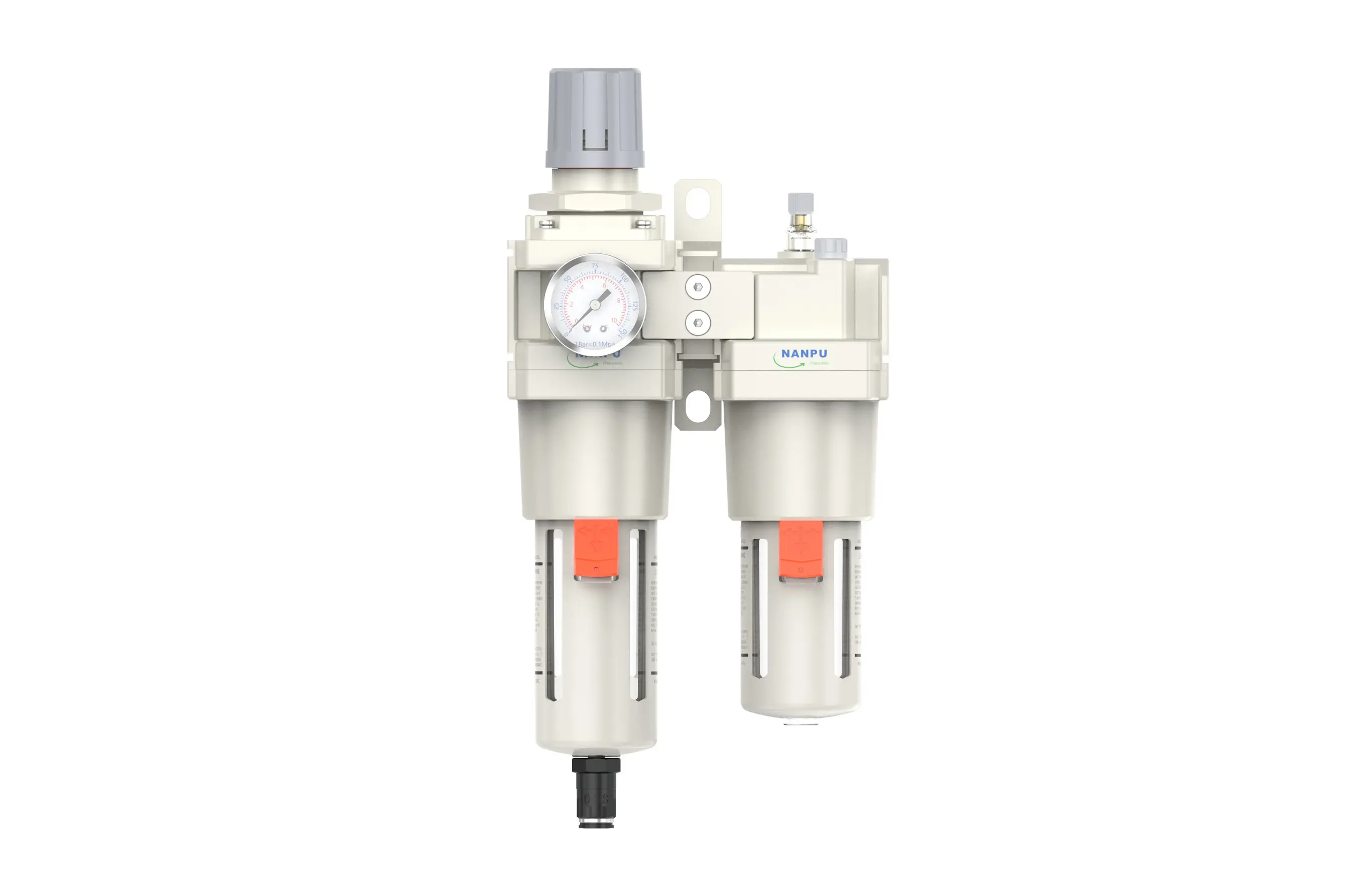
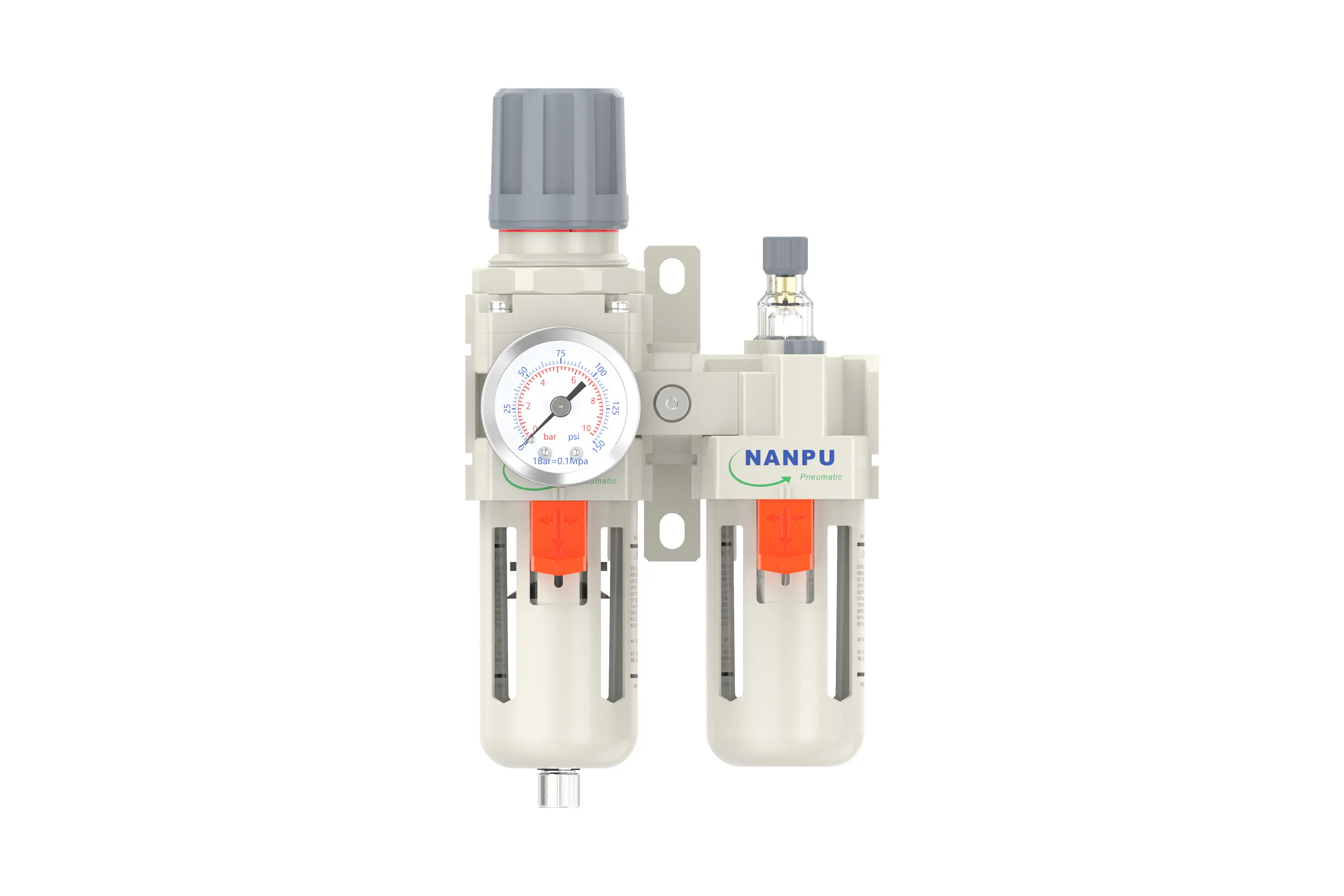
AC5010-06/AC5010-10 F.R.L.Combination Air Filter, Regulator & Lubricator
description1
AC5010-06/AC5010-10
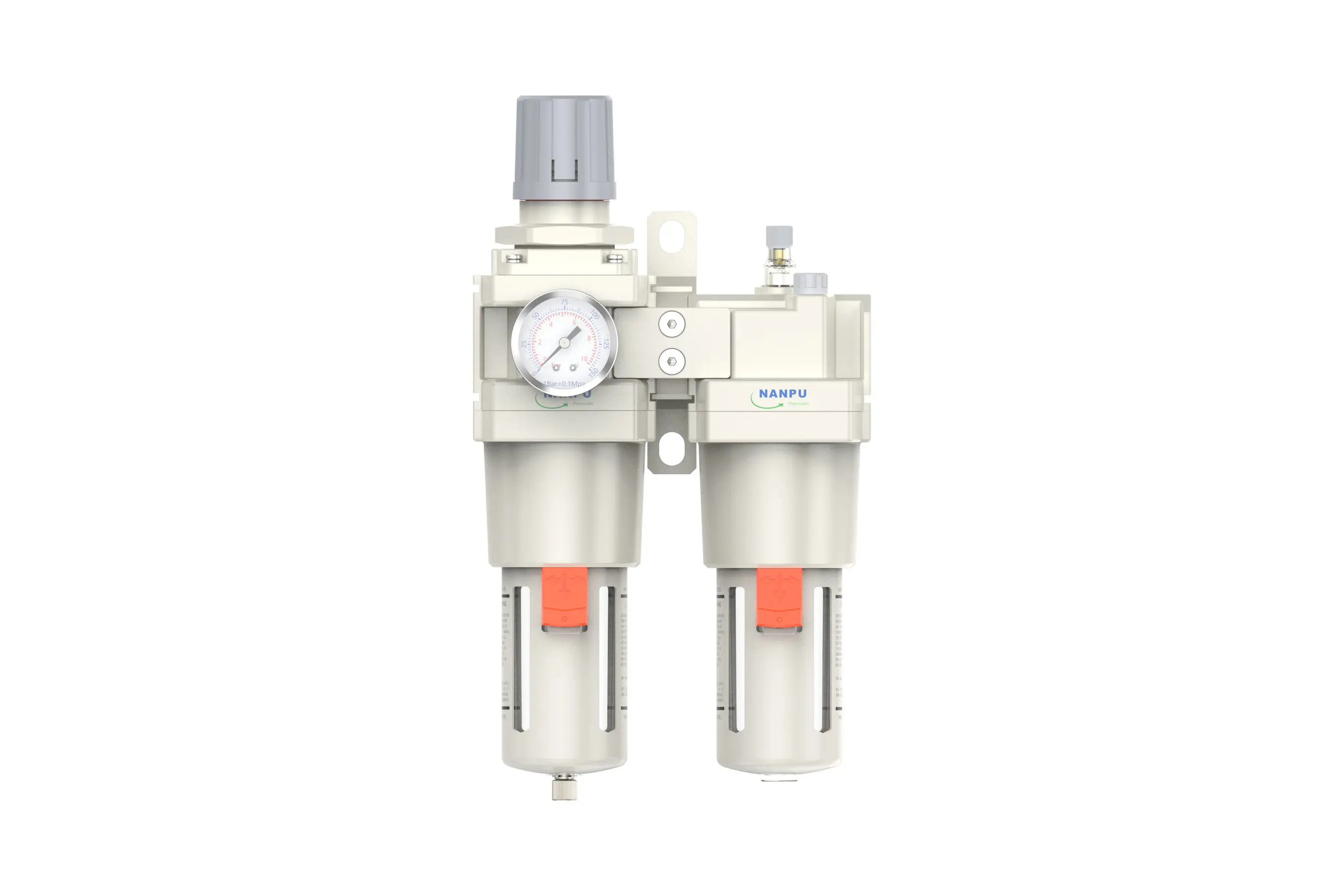
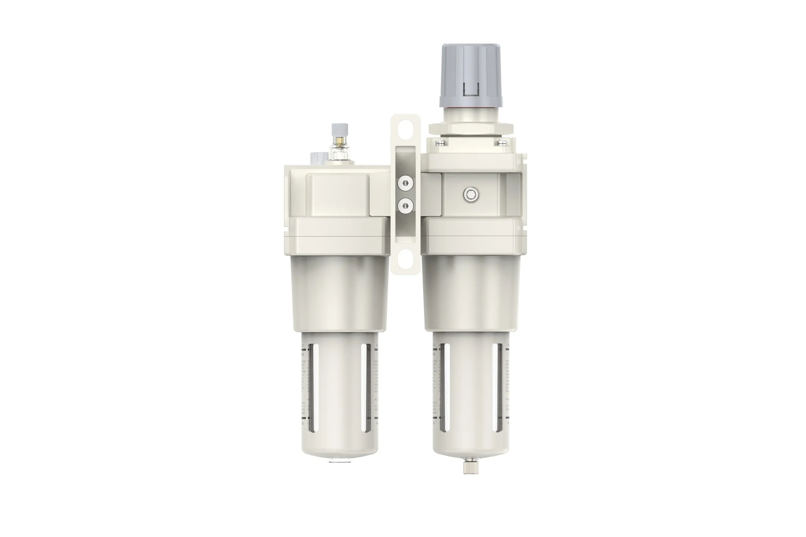
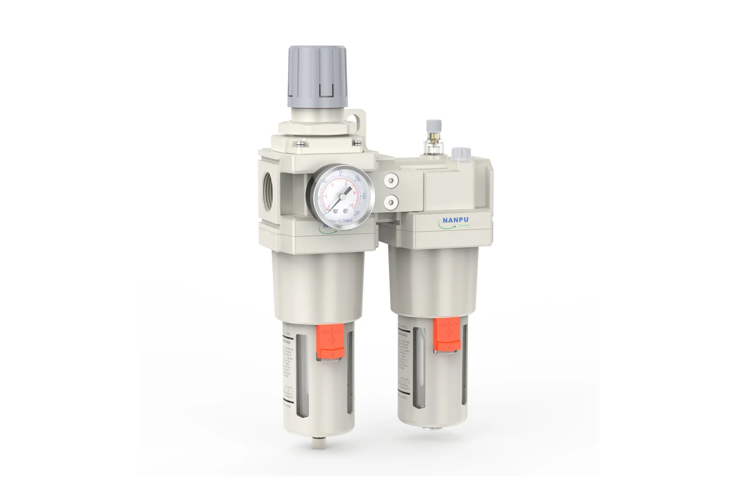
Manual Drain AC5010-06/AC5010-10 Portsize: 3/4" F.R.L.Combination Air Filter, Regulator & Lubricator
Auto Drain AC5010-06/AC5010-10 Portsize: 3/4" F.R.L.Combination Air Filter, Regulator & Lubricator
NANPUAC5010-06/AC5010-10
| AC | 5010 | 06 | BSP | D |
| Series Number | Body Size | Port Size | Thread Type | Drainage Method |
| 2000 | 02:1/4" | BSP | Blank: Differential Pressure Drain | |
| 3000 | 03:3/8" | NPT | A: Manual Drain | |
| 4000 | 04:1/2" | PT | D: Auto Drain | |
| 4000/5000 | 06: 3/4" | |||
| 5000 | 10: 1" |
NANPUTechnical Specifications
| Model | Model | |
| Manual Drain | Auto Drain | (L/min)Rated Flow Rate |
| AC2010-02 | AC2010-02D | 500 |
| AC3010-02 | AC3010-02D | 2000 |
| AC3010-03 | AC3010-03D | 2000 |
| AC4010-04 | AC4010-04D | 4000 |
| AC4010-06 | AC4010-06D | 4500 |
| AC5010-06 | AC5010-06D | 5000 |
| AC5010-10 | AC5010-10D | 5000 |
| Max Input Pressure | 1.2Mpa{12.24kgf/cm²} /174.04Psi |
| Max Operating Pressure | 1.0Mpa{10.2kgf/cm²} /145Psi |
| Temperature Range | 5~60℃ |
| Filtration Accuracy | 0.01μm, 5μm, 40μm |
| Bowl Material | Polycarbonate |
| Bowl Guard | AC2000 (None) AC3000~5000(YES) |
| Suggested Oil | Turbine Oil No. 1 ISO-VG32 |
| Pressure Range | AC2000~5000/0.05~0.85Mpa(0.51~8.7kgf/cm² )/0~125Psi |
1. Preparation
All calibration assemblies must comply with the maximum flow rate specifications.
Prior to installation, meticulously clean the ports and fittings to prevent the introduction of contaminants into the air pathway.
Ensure that the direction of the air flow aligns with the arrow markings on the product body, and verify that the port and thread dimensions are properly matched.
2. Pressure Adjustment
Lift the pressure gauge knob and perform the following rotation operations:
When rotating the knob in a clockwise direction, the pressure will increase in a stable manner. Conversely, counterclockwise rotation will result in a decrease in pressure.
Once the desired pressure value is achieved, cease rotation and secure the knob in place. Failure to complete this locking step may lead to potential leakage issues.
3. Dial Reading
Verify that the pressure gauge is firmly mounted on the main assembly. During pressure adjustment, closely monitor the gauge to ensure that the readings ascend and descend in a consistent and unimpeded manner.
4. Drainage
The drainage column is designed to operate automatically. It will open to discharge when there is no pressure and close upon the passage of airflow. When the water level exceeds the upper limit, immediate drainage is required; otherwise, it will lead to suboptimal dehumidification performance. The fitting on the drain head is intended for air hose connection and can be removed as per operational requirements.
5. Oil Adjustment
Turn the needle valve in the positive ("+") direction to enhance the oil suction rate. Conversely, rotating the needle valve in the negative ("-") direction will decelerate or terminate the oil suction process.
6. Refueling
Rotate the refueling screw in a clockwise direction, ensuring that the volume of oil added does not surpass 80% of the bowl's capacity. Post - refueling, securely tighten the refueling screw to maintain proper sealing and functionality.