


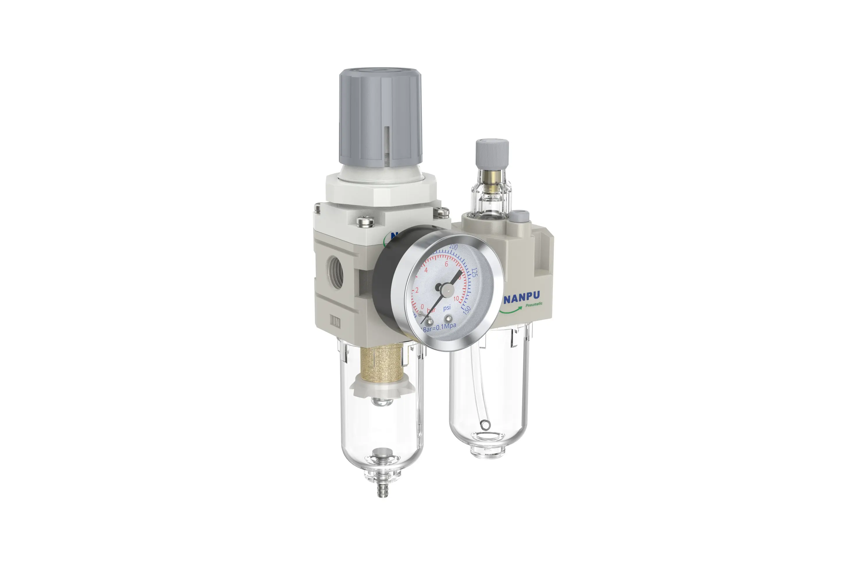
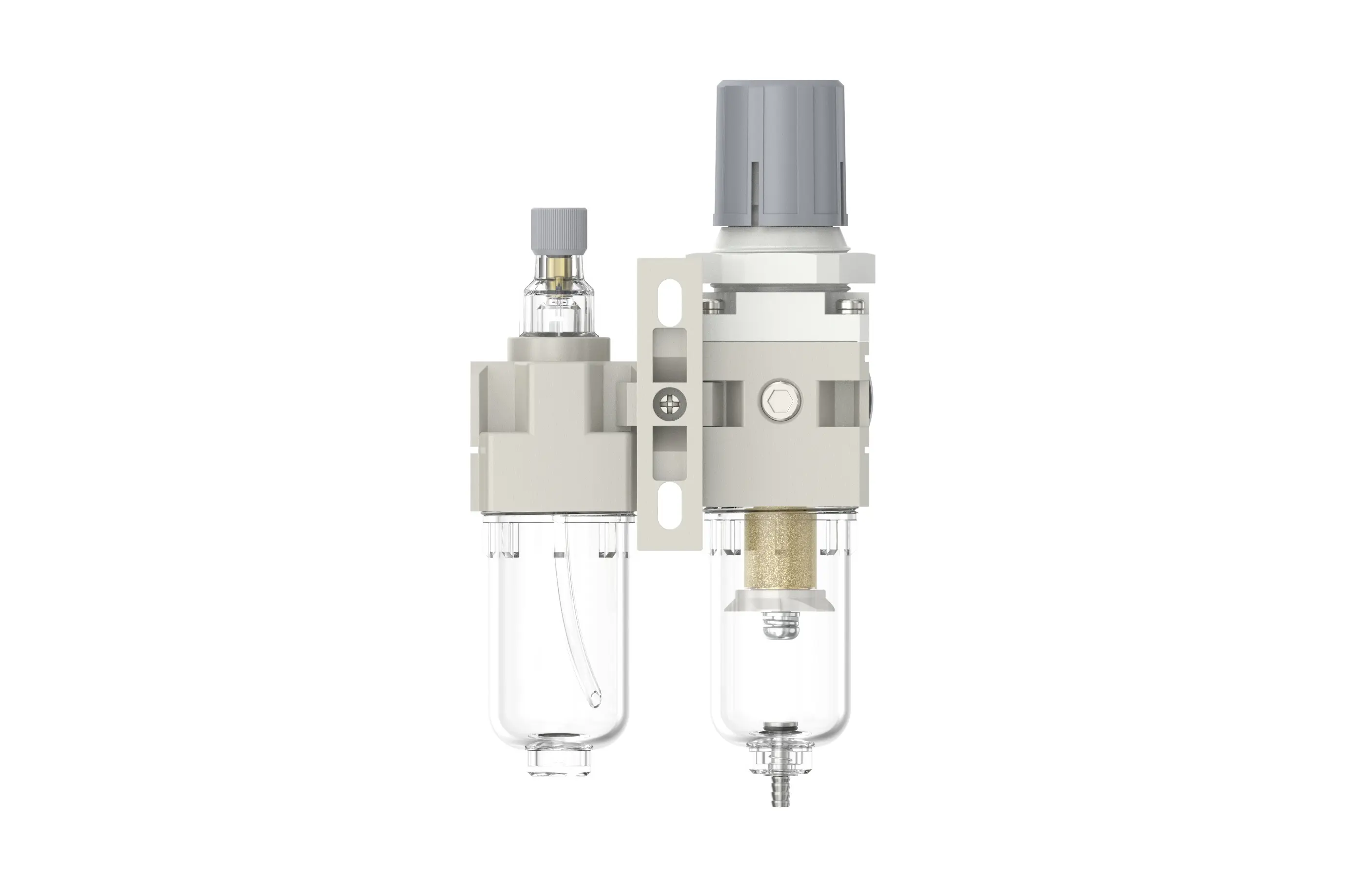
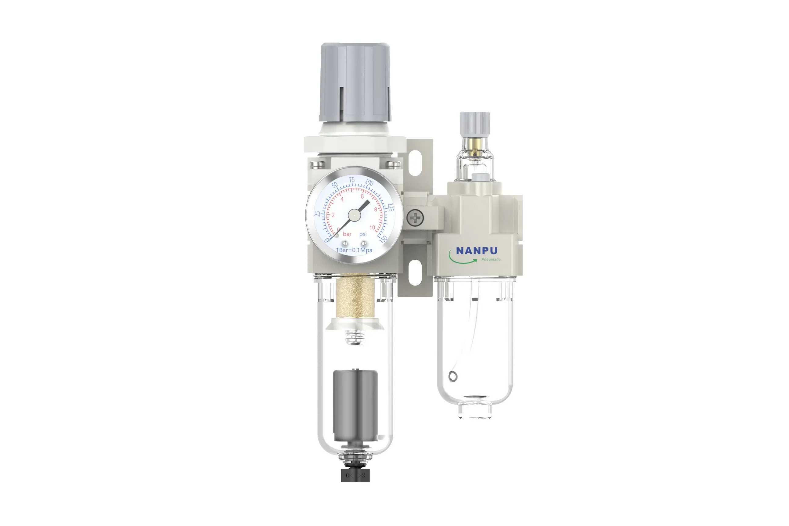
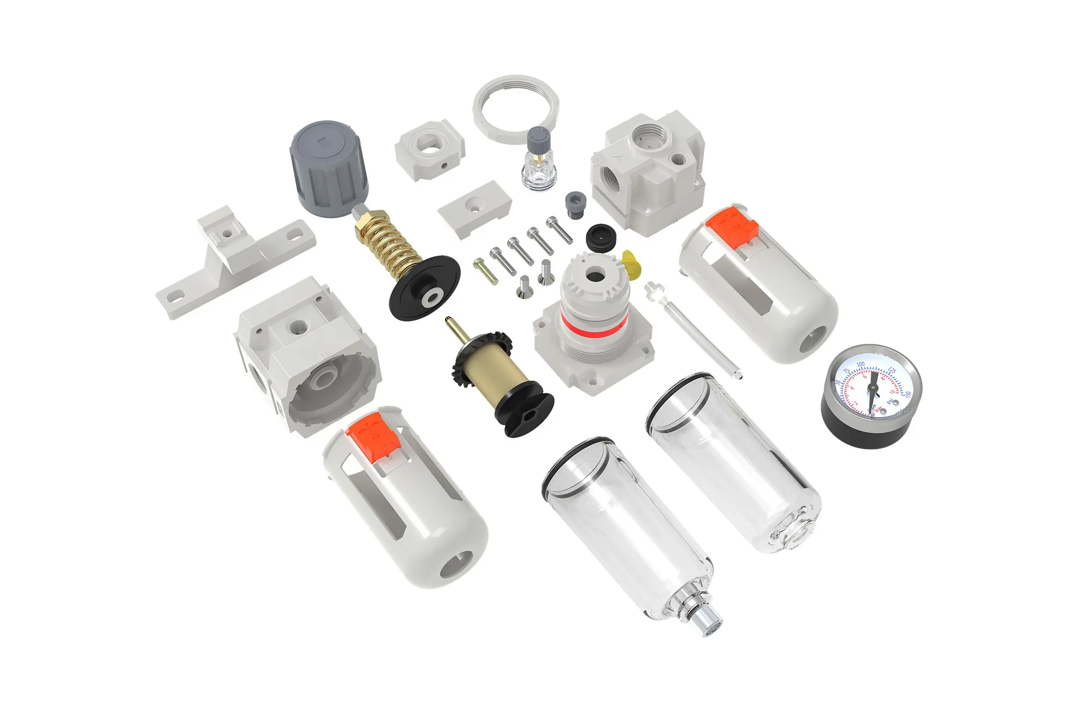
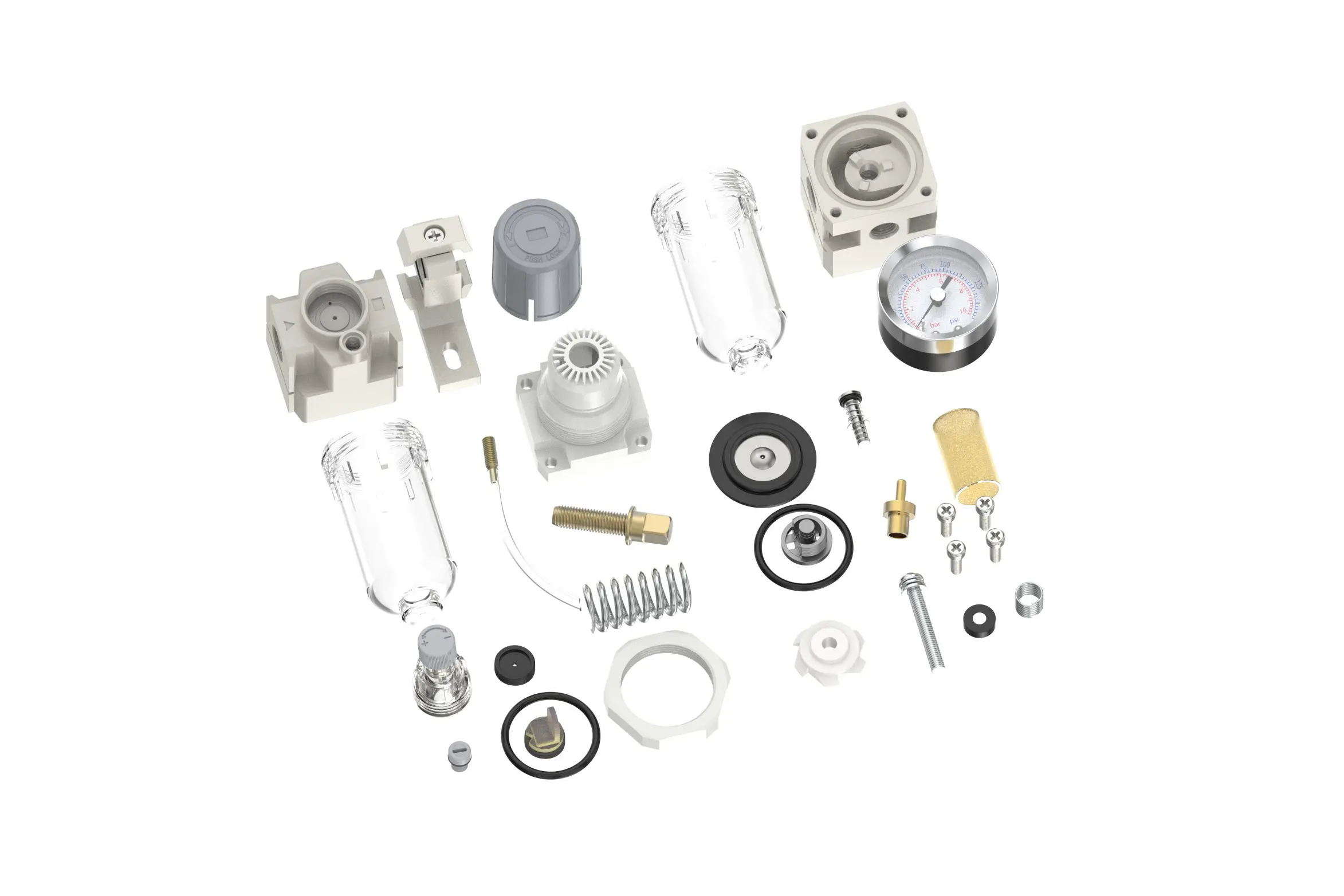
AC2010-02/AC2010-02D F.R.L.Combination Air Filter, Regulator & Lubricator
description1
AC2010-02/AC2010-02D
Manual Drain AC2010-02 Portsize:1/4" F.R.L.Combination Air Filter, Regulator & Lubricator
Auto Drain AC2010-02D Portsize:1/4" F.R.L.Combination Air Filter, Regulator & Lubricator
NANPUAC2010-02/AC2010-02D F.R.L.Combination Air Filter, Regulator & Lubricator
| AC | 2010 | 02 | BSP | D |
| Series Number | Body Size | Port Size | Thread Type | Drainage Method |
| 2000 | 02:1/4" | BSP | Blank: Differential Pressure Drain | |
| 3000 | 03:3/8" | NPT | A: Manual Drain | |
| 4000 | 04:1/2" | PT | D: Auto Drain | |
| 4000/5000 | 06: 3/4" | |||
| 5000 | 10: 1" |
NANPUTechnical Specifications
| Model | Model | |
| Manual Drain | Auto Drain | (L/min)Rated Flow Rate |
| AC2010-02 | AC2010-02D | 500 |
| AC3010-02 | AC3010-02D | 2000 |
| AC3010-03 | AC3010-03D | 2000 |
| AC4010-04 | AC4010-04D | 4000 |
| AC4010-06 | AC4010-06D | 4500 |
| AC5010-06 | AC5010-06D | 5000 |
| AC5010-10 | AC5010-10D | 5000 |
| Max Input Pressure | 1.2Mpa{12.24kgf/cm²} /174.04Psi |
| Max Operating Pressure | 1.0Mpa{10.2kgf/cm²} /145Psi |
| Temperature Range | 5~60℃ |
| Filtration Accuracy | 0.01μm, 5μm, 40μm |
| Bowl Material | Polycarbonate |
| Bowl Guard | AC2000 (None) AC3000~5000(YES) |
| Suggested Oil | Turbine Oil No. 1 ISO-VG32 |
| Pressure Range | AC2000~5000/0.05~0.85Mpa(0.51~8.7kgf/cm² )/0~125Psi |
1. Preparation
Every calibration component must meet the maximum flow rate requirement.
Before installation, meticulously scrub all ports and connectors to stop dust from infiltrating the air pathway.
Make sure that the air flow orientation aligns precisely with the arrow signs on the product casing, and check that port and thread sizes are correctly coordinated.
2. Pressure Adjustment
Raise the pressure gauge knob and start turning:
Turning it clockwise will steadily boost the pressure in a consistent way, whereas turning it counterclockwise will reduce it.
Stop turning when the target pressure level is reached and firmly push down the knob. Failing to do this may cause pressure seepage problems.
3. Dial Reading
Make sure the pressure gauge is firmly attached to the main structure. When adjusting the pressure, closely observe the gauge to confirm that the measurements rise and fall evenly.
4. Drainage
The drainage valve functions autonomously. When there is no pressure, it will unlock to release moisture, and it will seal shut as air passes through. Once the water level hits or surpasses the permitted maximum, prompt draining is essential; failing to do so will lead to reduced dehumidification efficiency. The fitting on the drainage unit is intended for connecting an air hose and can be readily removed according to particular operating needs.
5. Oil Adjustment
Rotate the needle valve clockwise to elevate the oil uptake speed. On the contrary, turning the needle valve counterclockwise will lower the oil uptake speed or bring it to a complete stop.
6. Refueling
Turn the filling screw in a clockwise manner. The amount of oil introduced must not surpass 80% of the container's capacity. After the refilling process is finished, firmly fasten the filling screw.