


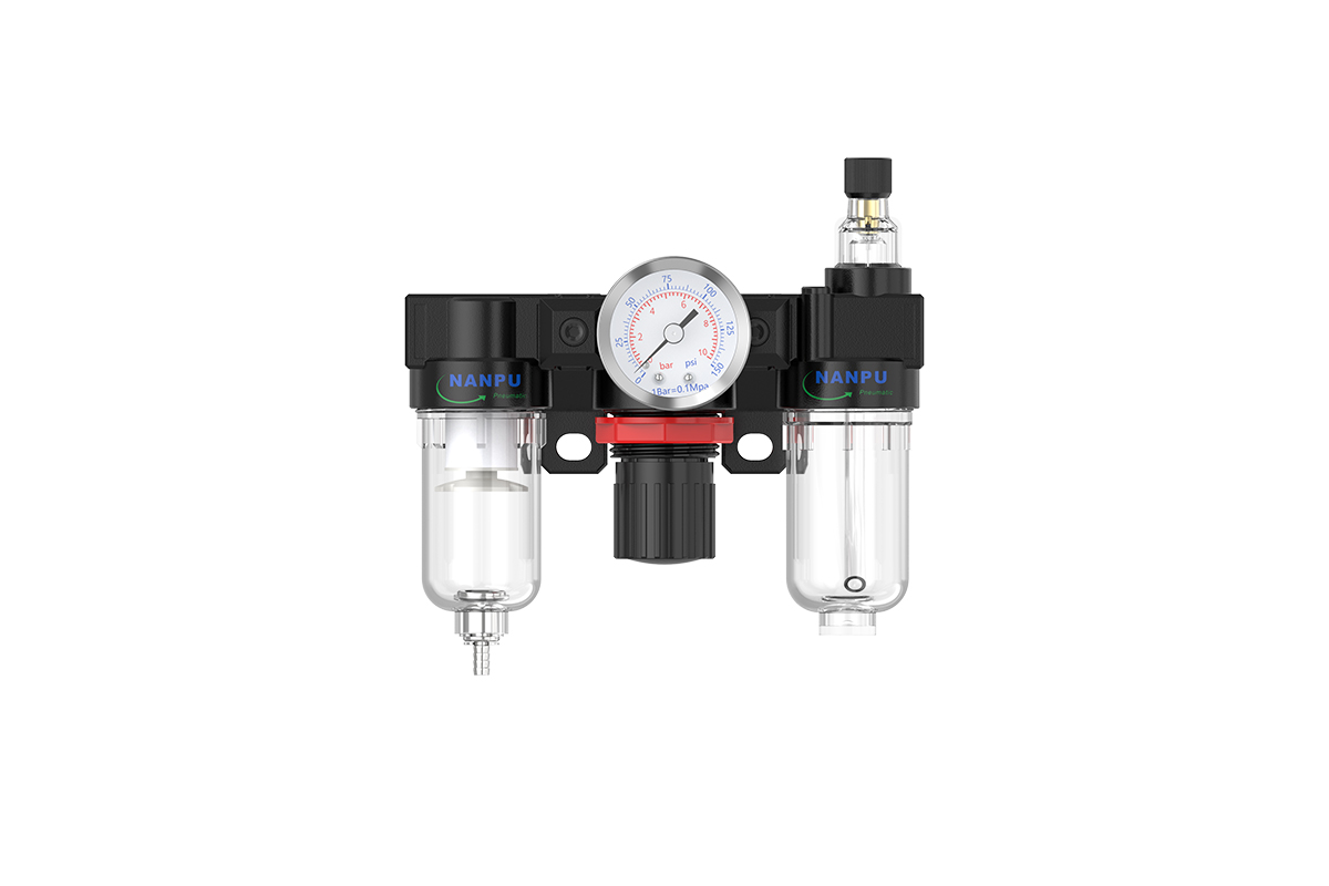
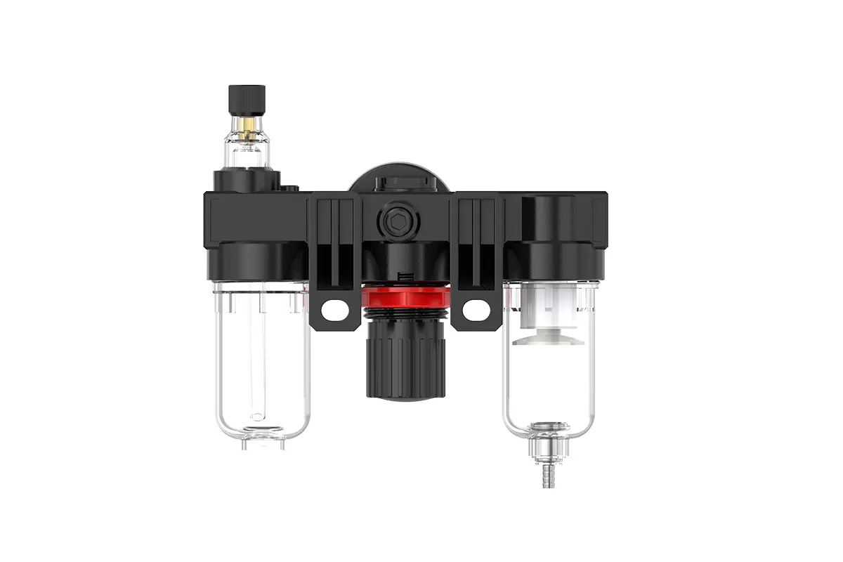
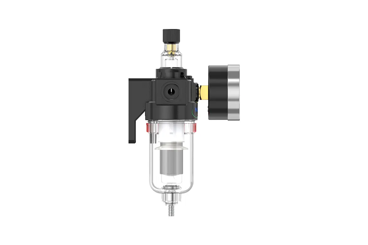
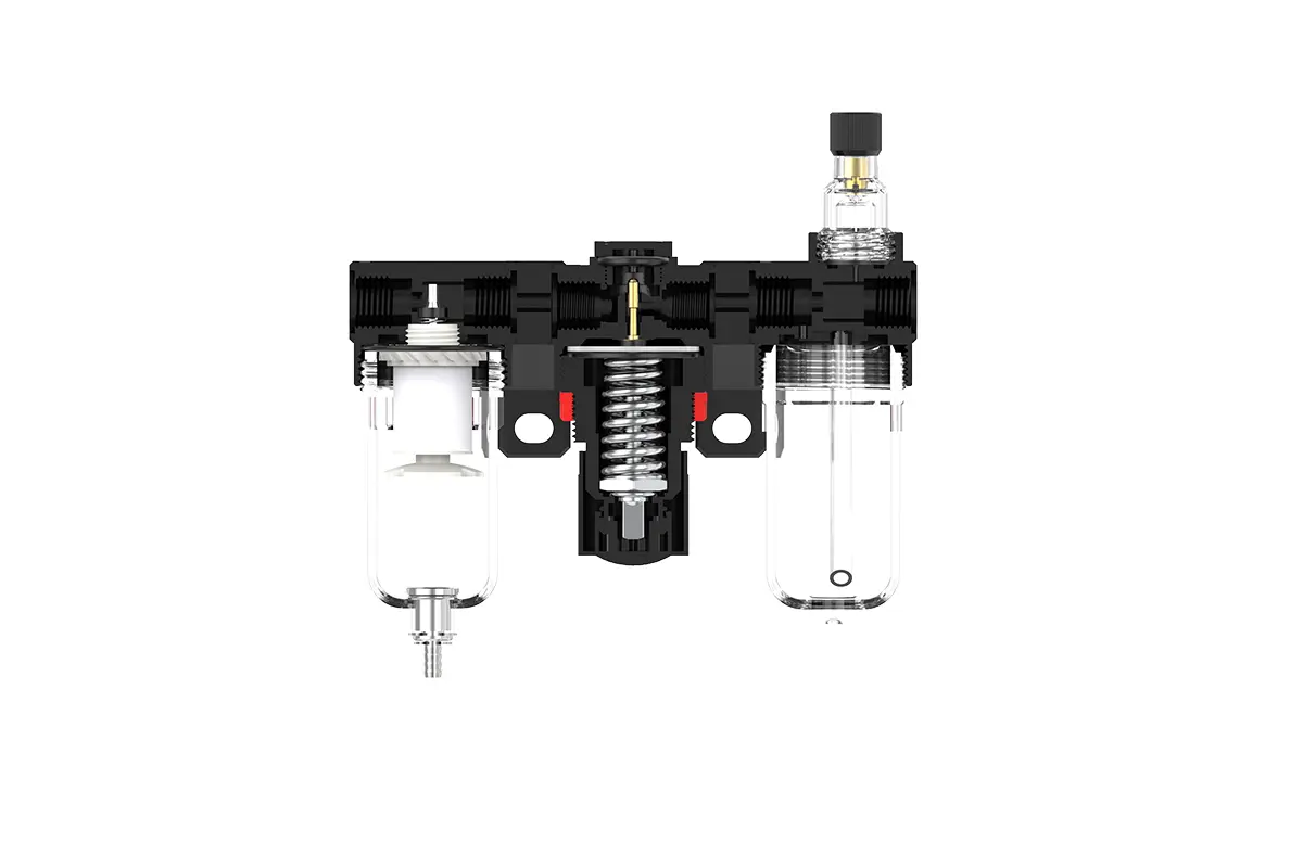
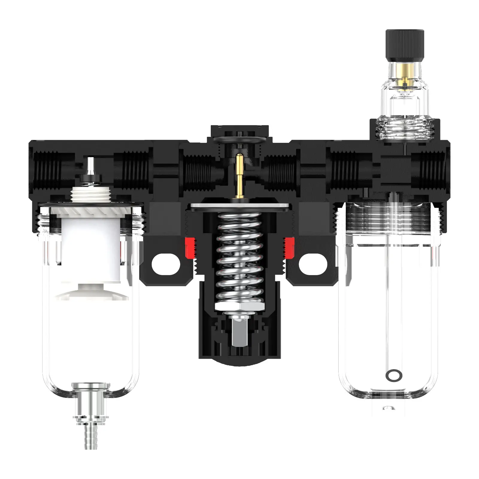
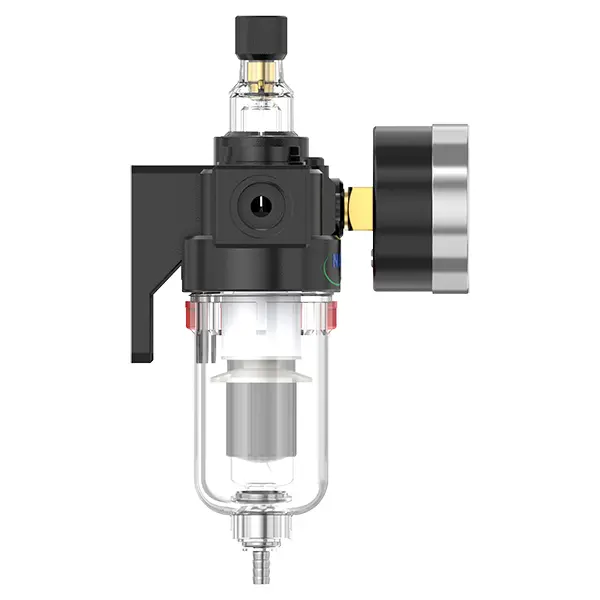
AC2000 1/4" F.R.L.Combination Air Filter, Regulator & Lubricator
description1

AC2000/AC2000-D
Manual Drain AC2000 1/4" F.R.L.Combination Air Filter, Regulator & Lubricator
Auto Drain AC2000-D 1/4" F.R.L.Combination Air Filter, Regulator & Lubricator
NANPUAC2000 1/4" F.R.L.Combination Air Filter, Regulator & Lubricator
| AC | 2000 | BSP | D | |
| Series Number | Body Size | Port Size | Thread Type | Drainage Method |
| 2000 | 02:1/4" | BSP | Blank: Differential Pressure Drain | |
| 3000 | 03:3/8" | NPT | A: Manual Drain | |
| 4000 | 04:1/2" | PT | D: Auto Drain |
NANPUTechnical Specifications
| Parameter | Value | |
| Max Input Pressure | 1.0Mpa(10.2kgf/cm²) 145Psi | |
| Max Operating Pressure | 1.0Mpa(10.2kgf/cm²) 145Psi | |
| Temperature Range | 5-60℃ | |
| Filtration Accuracy | 5μm、40μm | |
| Bowl Material | Polycarbonate | |
| Bowl Guard | AFC2000 (None) BFC2000-4000 (YES) | |
| Suggested Oil | Turbine Oil No. 1 ISO-VG32 | |
| Pressure Range | AC/BC 0.05-0.85Mpa (0.51-8.7kgf/cm²) 0-125Psi | |
| Model Manual Drain |
Model Auto Drain |
(L/min) Rated Flow Rate |
| AC2000 | AC2000-D | 850 |
| BC2000 | BC2000-D | 1400 |
| BC3000 | BC3000-D | 1400 |
| BC4000 | BC4000-D | 1400 |
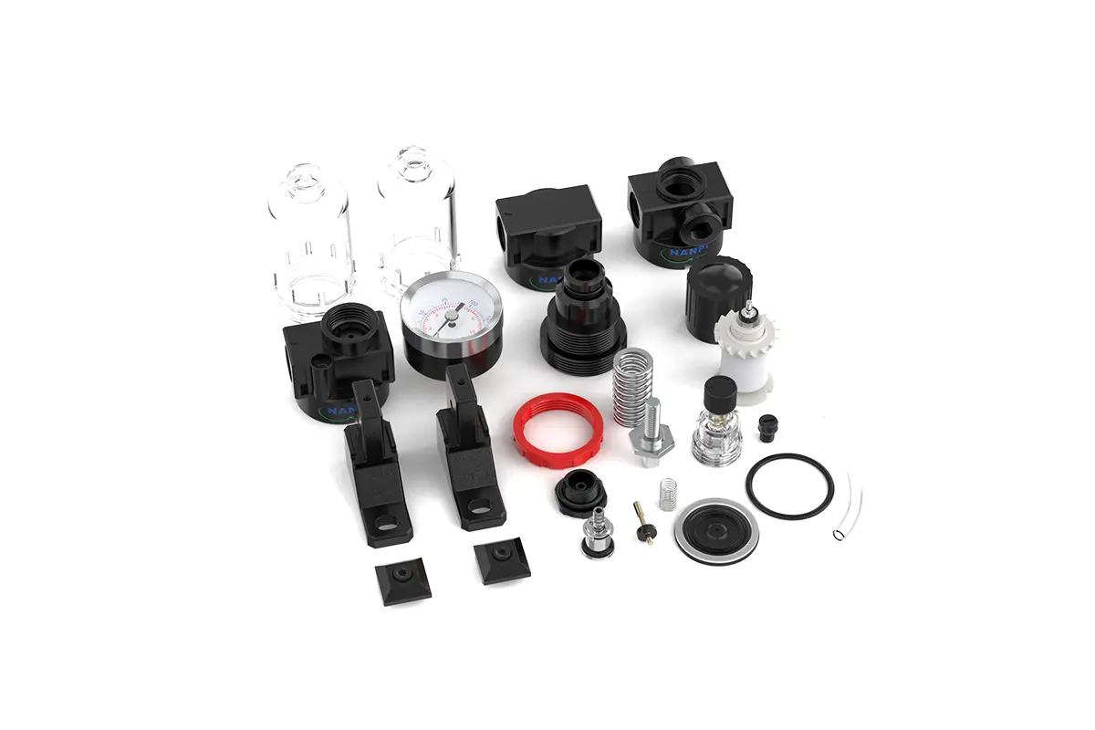
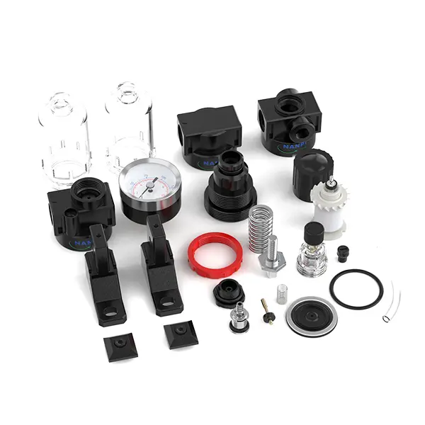
| Product Benefits |
| All Portsize Piggyback Air Filter (5 Micron Element Standard), Regulator & Lubricator (FRL) |
| Dry Air, Pressure Regulating & Lubricate Air |
| Temperature Range: 41-140℉ (5-60℃) |
NANPU Installation and Operating
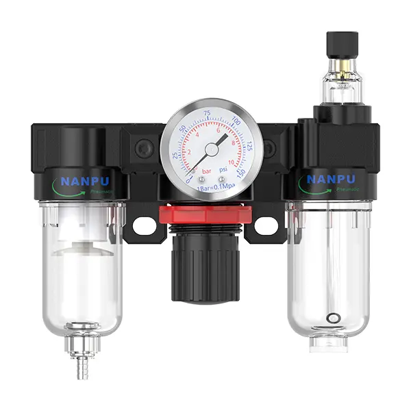
2. Pressure Adjustment Lift the pressure gauge knob and commence rotation: Clockwise rotation shall progressively increase pressure in a consistent manner, whereas counterclockwise rotation will effect a decrease. Discontinue rotation upon reaching the target pressure, then firmly depress the knob. Failure to secure the knob may lead to pressure leakage complications.
3. Dial Reading
Ensure the pressure gauge is rigidly mounted to the main structure. During pressure adjustment, closely monitor the gauge to validate that the readings increase and decrease in a uniform manner.
4. Drainage
The drainage valve functions in an automated mode. In the absence of pressure, it opens to expel condensate and seals when air flow is initiated. When the water level reaches or exceeds the permissible threshold, immediate drainage is mandatory; failure to do so will compromise dehumidification efficiency. The coupling on the drainage assembly is designed for air hose connection and can be readily detached in accordance with specific operational requirements.
5. Oil Adjustment
Rotate the metering valve clockwise to augment the lubricant intake rate. Conversely, rotating the valve counterclockwise shall reduce the flow incrementally until complete cessation is achieved.
6. Refueling
Rotate the filler cap clockwise. The volume of lubricant introduced must not exceed 80% of the reservoir capacity. Upon completion of the refilling procedure, ensure the filler cap is securely tightened to specifications.