


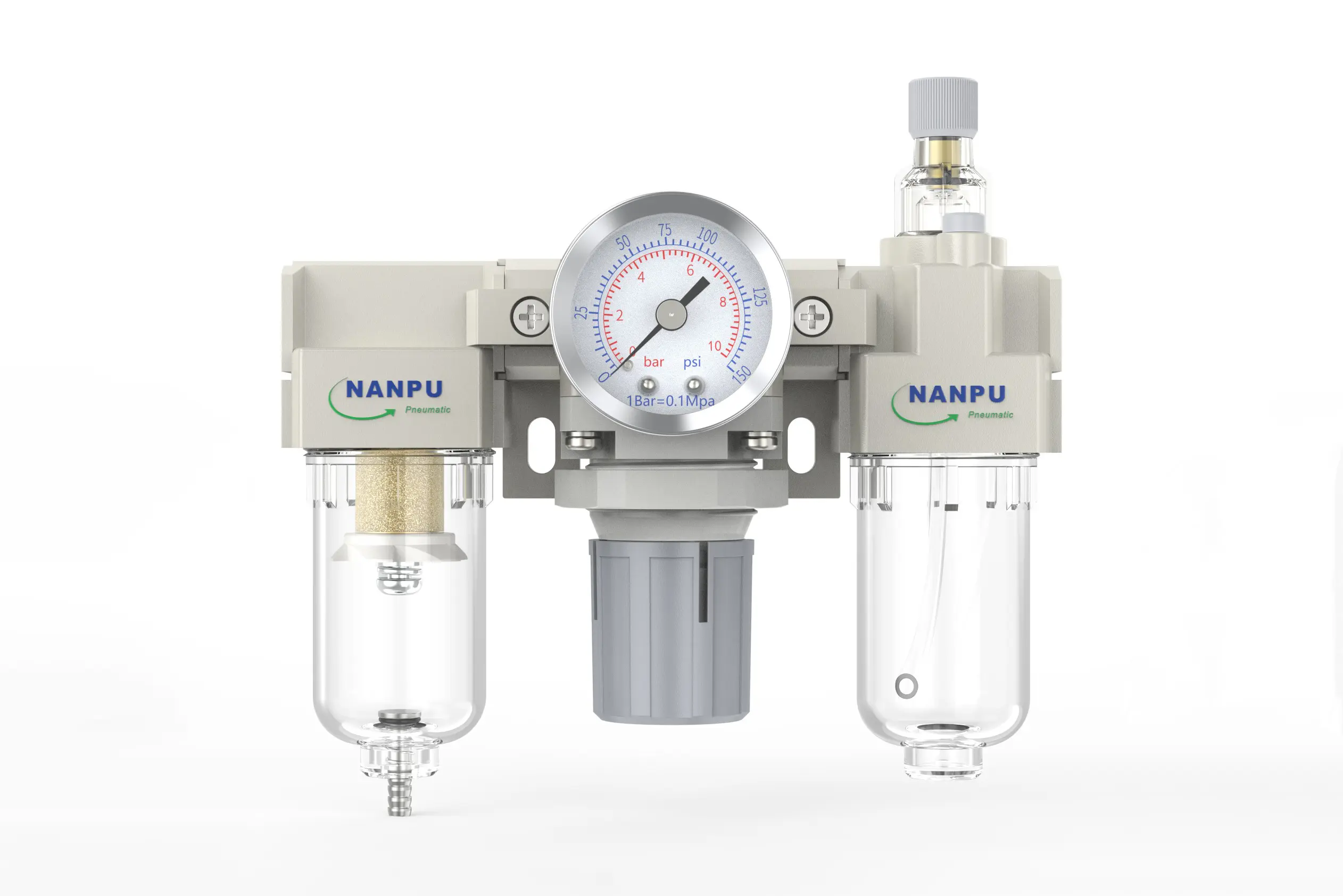
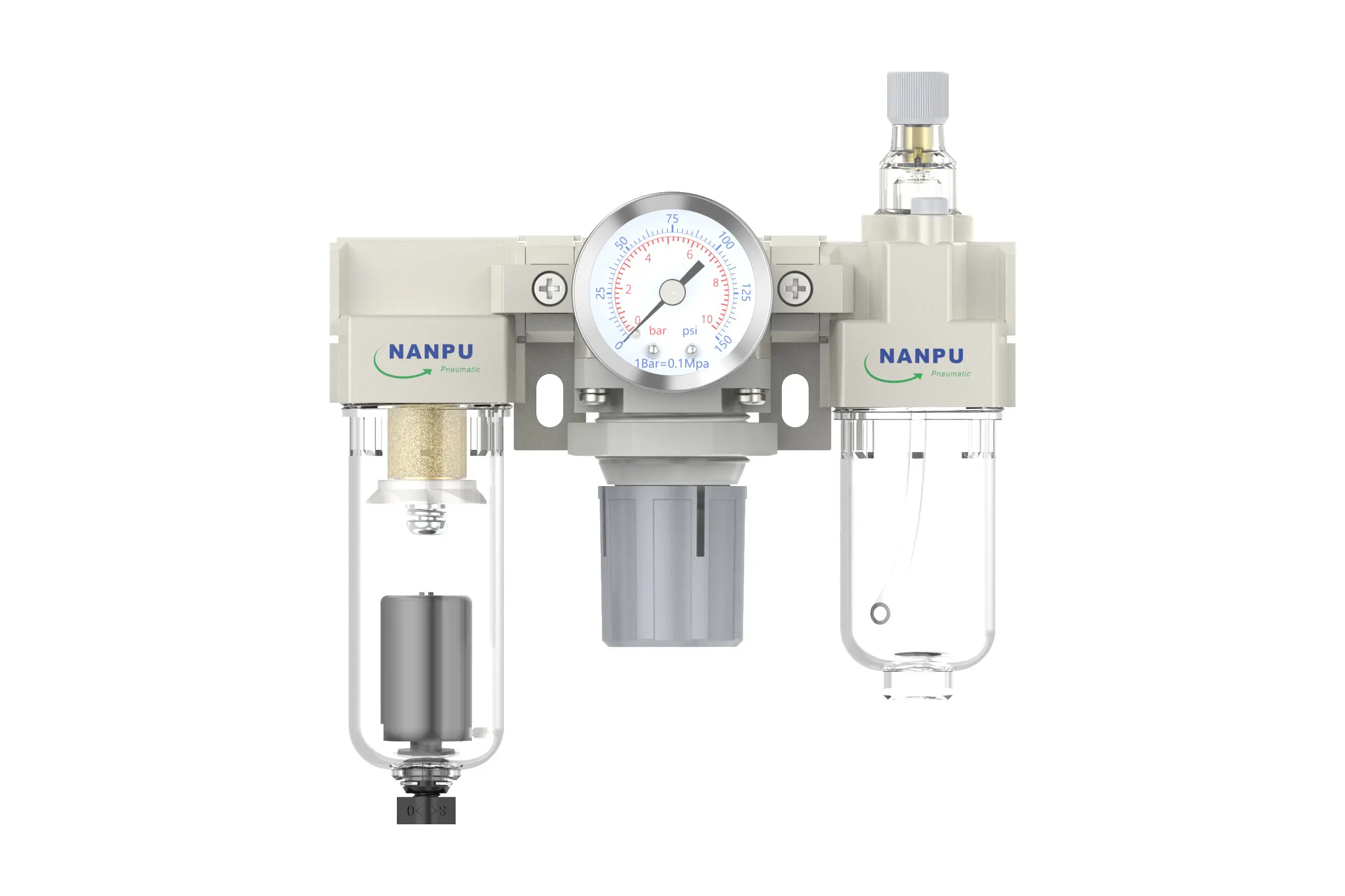
AC2000-02/AC2000-02D F.R.L.Combination Air Filter, Regulator & Lubricator
description1
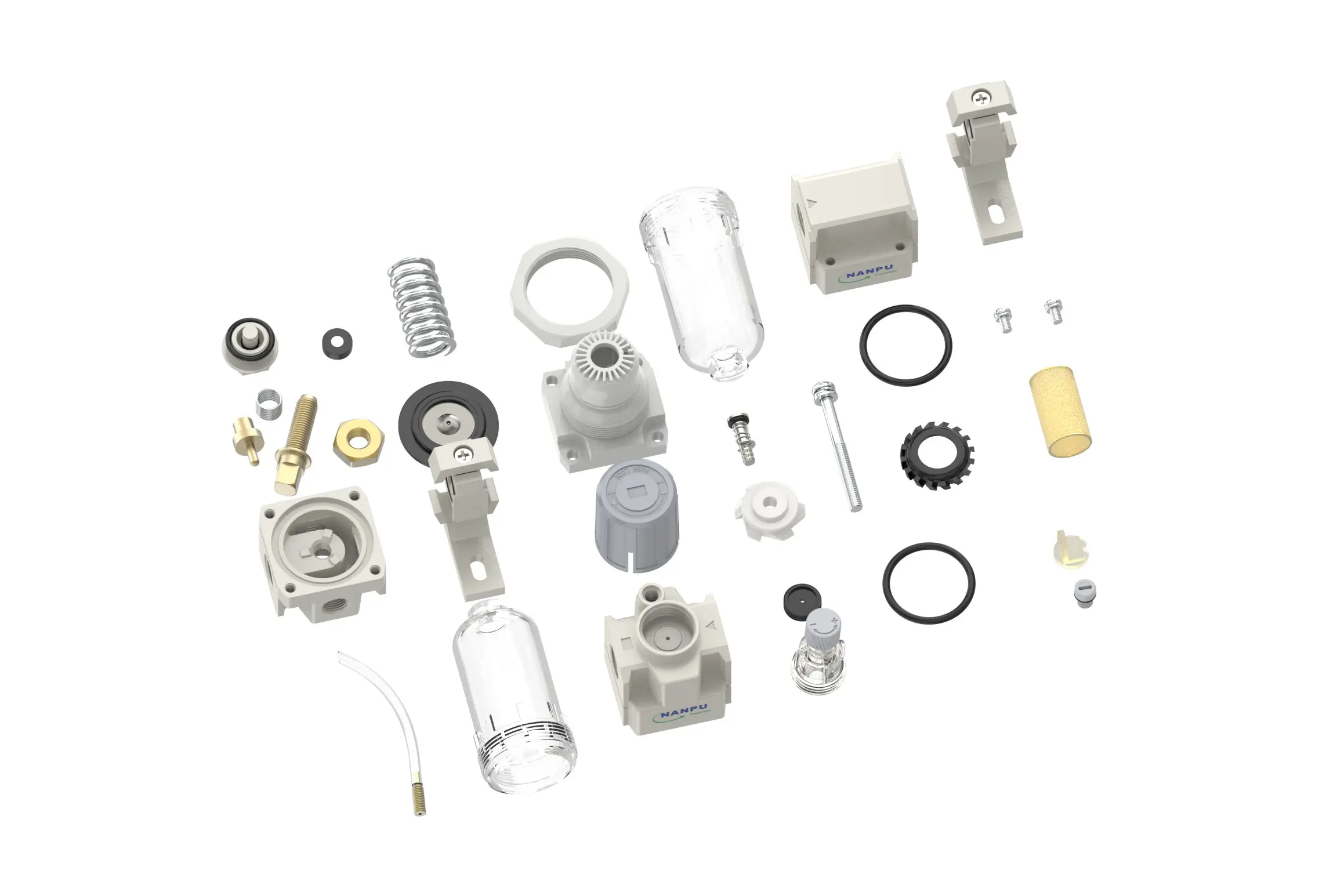
AC2000-02/AC2000-02D
Manual Drain AC2000-02 Portsize:1/4" F.R.L.Combination Air Filter, Regulator & Lubricator
Auto Drain AC2000-02D Portsize:1/4" F.R.L.Combination Air Filter, Regulator & Lubricator
NANPUAC2000-02/AC2000-02D
| AC | 2000 | 02 | BSP | D |
| Series Number | Body Size | Port Size | Thread Type | Drainage Method |
| 2000 | 02:1/4" | BSP | Blank: Differential Pressure Drain | |
| 3000 | 03:3/8" | NPT | A: Manual Drain | |
| 4000 | 04:1/2" | PT | D: Auto Drain | |
| 4000/5000 | 06: 3/4" | |||
| 5000 | 10: 1" |
NANPUTechnical Specifications
| Model | Model | |
| Manual Drain | Auto Drain | (L/min)Rated Flow Rate |
| AC2000-02 | AC2000-02D | 500 |
| AC3000-02 | AC3000-02D | 2000 |
| AC3000-03 | AC3000-03D | 2000 |
| AC4000-04 | AC4000-04D | 4000 |
| AC4000-06 | AC4000-06D | 4500 |
| AC5000-06 | AC5000-06D | 5000 |
| AC5000-10 | AC5000-10D | 5000 |
| Max Input Pressure | 1.2Mpa{12.24kgf/cm²} /174.04Psi |
| Max Operating Pressure | 1.0Mpa{10.2kgf/cm²} /145Psi |
| Temperature Range | 5~60℃ |
| Filtration Accuracy | 0.01μm, 5μm, 40μm |
| Bowl Material | Polycarbonate |
| Bowl Guard | AC2000 (None) AC3000~5000(YES) |
| Suggested Oil | Turbine Oil No. 1 ISO-VG32 |
| Pressure Range | AC2000~5000/0.05~0.85Mpa(0.51~8.7kgf/cm² )/0~125Psi |
1. Pre-Installation Preparation
All calibration assemblies shall be configured to accommodate peak flow demands (Qmax ≥125% nominal rating) while maintaining pneumatic circuit integrity.
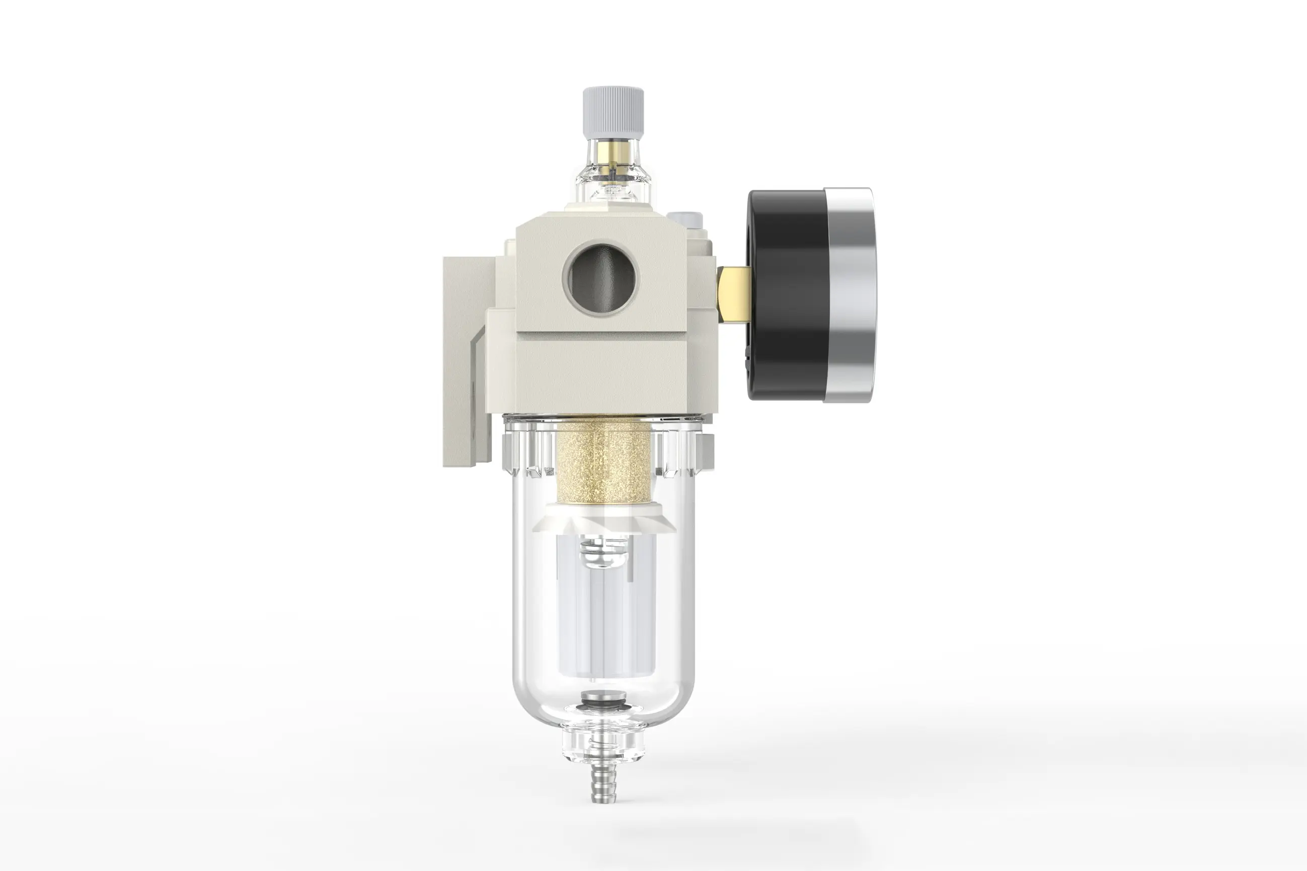
2. Pressure Adjustment
To adjust the pressure, turn the knob of the pressure gauge:
Rotate clockwise, and the pressure will steadily increase. Counterclock rotation will result in a decrease in pressure.
After reaching the desired scale, stop turning and lock the knob. Forgetting this step may lead to leakage issues.
3. Pressure Gauge Reading
Please ensure that the pressure gauge is securely installed on the main body and pay attention to the reading when adjusting the pressure to ensure it rises falls steadily.
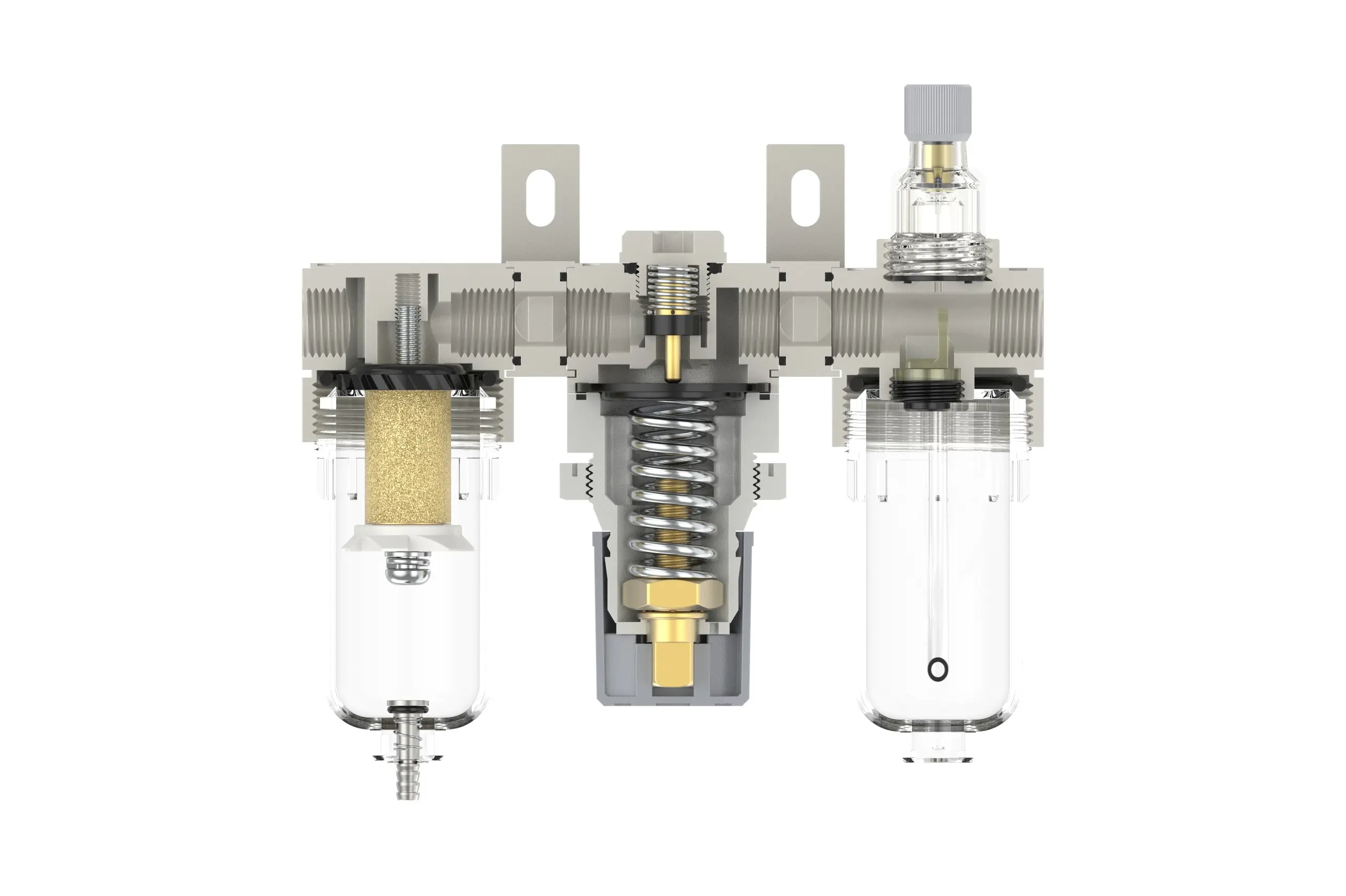
4. Drainage
In the absence of pressure, the drainage column will automatically discharge and close when there is airflow. Draining must be performed when the water exceeds the upper limit to avoid poor wet effect.
The accessories on the drainage head can be used to connect an air hose, and you can also disassemble them freely as.
5. Oil Level Adjustment
Turn the needle valve counterclockwise to increase the oil absorption speed. When turning clockwise to the "-" direction, the speed slow down and stop.
6. Refueling
Turn the refueling screw clockwise, and the added oil should not exceed 80% of the fuel tank. After refing, please tighten the refueling screw.